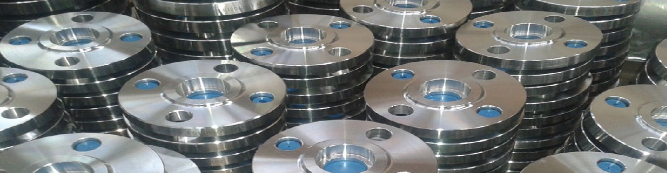
We are the supply of lapped joint flanges that are manufactured in compliance with the industrial standards. Used on pipes fitted with lapped pipe or with lap joint stub ends etc., these flanges can be availed in standard as well as customized dimensions.
Email : office@ashapuraequipment.com, Mobile : +91-8419925080
API 6A Type 6B Flanges
| Class | Size | OD | K | T | X | BC | Num of Bolts | Bolt Hole Dia | R/RX Ring Num |
| 2,000 psi (130 bar) Working Pressure | 2-1/6 | 6.50 | 4.25 | 1.31 | 3.31 | 5.00 | 8 | 0.75 | 23 |
| 2-9/16 | 7.50 | 5.00 | 1.44 | 3.94 | 5.88 | 8 | 0.88 | 26 | |
| 3-1/8 | 8.25 | 5.75 | 1.56 | 4.62 | 6.62 | 8 | 0.88 | 31 | |
| 4-1/16 | 10.75 | 6.88 | 1.81 | 6.00 | 8.50 | 8 | 1.00 | 37 | |
| 5-1/8 | 13.00 | 8.25 | 2.06 | 7.44 | 10.50 | 8 | 1.12 | 41 | |
| 7-1/16 | 14.00 | 9.50 | 2.19 | 8.75 | 11.50 | 12 | 1.12 | 45 | |
| 9 | 16.50 | 11.88 | 2.50 | 10.75 | 13.75 | 12 | 1.25 | 49 | |
| 11 | 20.00 | 14.00 | 2.81 | 13.50 | 17.00 | 16 | 1.38 | 53 | |
| 13-5/8 | 22.00 | 16.25 | 2.94 | 15.75 | 19.25 | 20 | 1.38 | 57 | |
| 16-3/4 | 27.00 | 20.00 | 3.31 | 19.50 | 23.75 | 20 | 1.62 | 65 | |
| 21-1/4 | 32.00 | 25.00 | 3.88 | 24.00 | 28.50 | 24 | 1.75 | 73 | |
| Class | Size | OD | K | T | X | BC | Num of Bolts | Bolt Hole Dia | R/RX Ring Num |
| 3,000 psi (207 bar) Working Pressure | 2-1/6 | 8.50 | 4.88 | 1.81 | 4.12 | 6.50 | 8 | 1.00 | 24 |
| 2-9/16 | 9.62 | 5.38 | 1.94 | 4.88 | 7.50 | 8 | 1.12 | 27 | |
| 3-1/8 | 9.50 | 6.12 | 1.81 | 5.00 | 7.50 | 8 | 1.00 | 31 | |
| 4-1/16 | 11.50 | 7.12 | 2.06 | 6.25 | 9.25 | 8 | 1.25 | 37 | |
| 5-1/8 | 13.75 | 8.50 | 2.31 | 7.50 | 11.00 | 8 | 1.38 | 41 | |
| 7-1/16 | 15.00 | 9.50 | 2.50 | 9.25 | 12.50 | 12 | 1.25 | 45 | |
| 9 | 18.50 | 12.12 | 2.81 | 11.75 | 15.50 | 12 | 1.50 | 49 | |
| 11 | 21.50 | 14.25 | 3.06 | 14.50 | 18.50 | 16 | 1.50 | 53 | |
| 13-5/8 | 24.00 | 16.50 | 3.44 | 16.50 | 21.00 | 20 | 1.50 | 57 | |
| 16-3/4 | 27.75 | 20.62 | 3.94 | 20.00 | 24.25 | 20 | 1.75 | 66 | |
| 20-3/4 | 33.75 | 25.50 | 4.75 | 24.50 | 29.50 | 20 | 2.12 | 74 | |
| Class | Size | OD | K | T | X | BC | Num of Bolts | Bolt Hole Dia | R/RX Ring Num |
| 5,000 psi (345 bar) Working Pressure | 2-1/16 | 8.50 | 4.88 | 1.81 | 4.12 | 6.50 | 8 | 1.00 | 24 |
| 2-9/16 | 9.62 | 5.38 | 1.94 | 4.88 | 7.50 | 8 | 1.12 | 27 | |
| 3-1/8 | 10.50 | 6.62 | 2.19 | 5.25 | 8.00 | 8 | 1.25 | 35 | |
| 4-1/16 | 12.25 | 7.62 | 2.44 | 6.38 | 9.50 | 8 | 1.38 | 39 | |
| 5-1/8 | 14.75 | 9.00 | 3.19 | 7.75 | 11.50 | 8 | 1.62 | 44 | |
| 7-1/16 | 15.50 | 9.75 | 3.62 | 9.00 | 12.50 | 12 | 1.50 | 46 | |
| 9 | 19.00 | 12.50 | 4.06 | 11.50 | 15.50 | 12 | 1.75 | 50 | |
| 11 | 23.00 | 14.63 | 4.69 | 14.50 | 19.00 | 12 | 2.00 | 54 |
Flanges are available as Weld Neck, Integral, Blinds, Targets and Test Blinds for use with the following pressure ratings:
| Max. Working Pressure | 2,000 PSI | 3,000 PSI | 5,000 PSI | 10,000 PSI | 15,000 PSI | 20,000 PSI | ||
| Test Pressure | 3,000 PSI | 4,500 PSI | 7,500 PSI | 15,000 PSI | 22,500 PSI | 30,000 PSI | ||
| Product Specification Levels | 1, 2, 3& 4 | 1, 2, 3& 4 | 1, 2, 3& 4 | 1, 2, 3& 4 | 1, 2, 3& 4 | 1, 2, 3& 4 | ||
| API Temperature Rating | K (-60 Deg C) | K (-60 Deg C) | K (-60 Deg C) | K (-60 Deg C) | K (-60 Deg C) | K (-60 Deg C) | ||
| To | To | To | To | To | To | |||
| Y (+345 Deg C) | Y (+345 Deg C) | Y (+345 Deg C) | Y (+345 Deg C) | Y (+345 Deg C) | Y (+345 Deg C) | |||
| Integral, Blind, Target Blind & Test Flanges | ||||||||
| Min. Yield | 60,000 PSI | 60,000 PSI | 60,000 PSI | 60,000 PSI | 75,000 PSI | 75,000 PSI | ||
| Min. Tensile | 85,000 PSI | 85,000 PSI | 85,000 PSI | 85,000 PSI | 95,000 PSI | 95,000 PSI | ||
| Material | API 60K | API 60K | API 60K | API 60K | API 75K | API 75K | ||
| Weld Neck Flanges | ||||||||
| Min. Yield | 45,000 PSI | 45,000 PSI | 45,000 PSI | 60,000 PSI | 75,000 PSI | 75,000 PSI | ||
| Min. Tensile | 70,000 PSI | 70,000 PSI | 70,000 PSI | 85,000 PSI | 95,000 PSI | 95,000 PSI | ||
| Material | API 45K | API 45K | API 45K | API 60K | API 75K | API 7 |
API 6A Type 6BX Flanges
| Class | Size | OD | K | T | X | BC | Num of Bolts | Bolt Hole Dia | R/RX Ring Num |
| 2,000 psi (130 bar) Working Pressure | 2-1/6 | 6.50 | 4.25 | 1.31 | 3.31 | 5.00 | 8 | 0.75 | 23 |
| 2-9/16 | 7.50 | 5.00 | 1.44 | 3.94 | 5.88 | 8 | 0.88 | 26 | |
| 3-1/8 | 8.25 | 5.75 | 1.56 | 4.62 | 6.62 | 8 | 0.88 | 31 | |
| 4-1/16 | 10.75 | 6.88 | 1.81 | 6.00 | 8.50 | 8 | 1.00 | 37 | |
| 5-1/8 | 13.00 | 8.25 | 2.06 | 7.44 | 10.50 | 8 | 1.12 | 41 | |
| 7-1/16 | 14.00 | 9.50 | 2.19 | 8.75 | 11.50 | 12 | 1.12 | 45 | |
| 9 | 16.50 | 11.88 | 2.50 | 10.75 | 13.75 | 12 | 1.25 | 49 | |
| 11 | 20.00 | 14.00 | 2.81 | 13.50 | 17.00 | 16 | 1.38 | 53 | |
| 13-5/8 | 22.00 | 16.25 | 2.94 | 15.75 | 19.25 | 20 | 1.38 | 57 | |
| 16-3/4 | 27.00 | 20.00 | 3.31 | 19.50 | 23.75 | 20 | 1.62 | 65 | |
| 21-1/4 | 32.00 | 25.00 | 3.88 | 24.00 | 28.50 | 24 | 1.75 | 73 | |
| Class | Size | OD | K | T | X | BC | Num of Bolts | Bolt Hole Dia | R/RX Ring Num |
| 3,000 psi (207 bar) Working Pressure | 2-1/6 | 8.50 | 4.88 | 1.81 | 4.12 | 6.50 | 8 | 1.00 | 24 |
| 2-9/16 | 9.62 | 5.38 | 1.94 | 4.88 | 7.50 | 8 | 1.12 | 27 | |
| 3-1/8 | 9.50 | 6.12 | 1.81 | 5.00 | 7.50 | 8 | 1.00 | 31 | |
| 4-1/16 | 11.50 | 7.12 | 2.06 | 6.25 | 9.25 | 8 | 1.25 | 37 | |
| 5-1/8 | 13.75 | 8.50 | 2.31 | 7.50 | 11.00 | 8 | 1.38 | 41 | |
| 7-1/16 | 15.00 | 9.50 | 2.50 | 9.25 | 12.50 | 12 | 1.25 | 45 | |
| 9 | 18.50 | 12.12 | 2.81 | 11.75 | 15.50 | 12 | 1.50 | 49 | |
| 11 | 21.50 | 14.25 | 3.06 | 14.50 | 18.50 | 16 | 1.50 | 53 | |
| 13-5/8 | 24.00 | 16.50 | 3.44 | 16.50 | 21.00 | 20 | 1.50 | 57 | |
| 16-3/4 | 27.75 | 20.62 | 3.94 | 20.00 | 24.25 | 20 | 1.75 | 66 | |
| 20-3/4 | 33.75 | 25.50 | 4.75 | 24.50 | 29.50 | 20 | 2.12 | 74 | |
| Class | Size | OD | K | T | X | BC | Num of Bolts | Bolt Hole Dia | R/RX Ring Num |
| 5,000 psi (345 bar) Working Pressure | 2-1/16 | 8.50 | 4.88 | 1.81 | 4.12 | 6.50 | 8 | 1.00 | 24 |
| 2-9/16 | 9.62 | 5.38 | 1.94 | 4.88 | 7.50 | 8 | 1.12 | 27 | |
| 3-1/8 | 10.50 | 6.62 | 2.19 | 5.25 | 8.00 | 8 | 1.25 | 35 | |
| 4-1/16 | 12.25 | 7.62 | 2.44 | 6.38 | 9.50 | 8 | 1.38 | 39 | |
| 5-1/8 | 14.75 | 9.00 | 3.19 | 7.75 | 11.50 | 8 | 1.62 | 44 | |
| 7-1/16 | 15.50 | 9.75 | 3.62 | 9.00 | 12.50 | 12 | 1.50 | 46 | |
| 9 | 19.00 | 12.50 | 4.06 | 11.50 | 15.50 | 12 | 1.75 | 50 | |
| 11 | 23.00 | 14.63 | 4.69 | 14.50 | 19.00 | 12 | 2.00 | 54 |
Flanges are available as Weld Neck, Integral, Blinds, Targets and Test Blinds for use with the following pressure ratings:
| Max. Working Pressure | 2,000 PSI | 3,000 PSI | 5,000 PSI | 10,000 PSI | 15,000 PSI | 20,000 PSI | |
| Test Pressure | 3,000 PSI | 4,500 PSI | 7,500 PSI | 15,000 PSI | 22,500 PSI | 30,000 PSI | |
| Product Specification Levels | 1, 2, 3 & 4 | 1, 2, 3 & 4 | 1, 2, 3 & 4 | 1, 2, 3 & 4 | 1, 2, 3 & 4 | 1, 2, 3 & 4 | |
| API Temperature Rating | K (-60 Deg C) | K (-60 Deg C) | K (-60 Deg C) | K (-60 Deg C) | K (-60 Deg C) | K (-60 Deg C) | |
| To | To | To | To | To | To | ||
| Y (+345 Deg C) | Y (+345 Deg C) | Y (+345 Deg C) | Y (+345 Deg C) | Y (+345 Deg C) | Y (+345 Deg C) | ||
| Integral, Blind, Target Blind & Test Flanges | |||||||
| Min. Yield | 60,000 PSI | 60,000 PSI | 60,000 PSI | 60,000 PSI | 75,000 PSI | 75,000 PSI | |
| Min. Tensile | 85,000 PSI | 85,000 PSI | 85,000 PSI | 85,000 PSI | 95,000 PSI | 95,000 PSI | |
| Material | API 60K | API 60K | API 60K | API 60K | API 75K | API 75K | |
| Weld Neck Flanges | |||||||
| Min. Yield | 45,000 PSI | 45,000 PSI | 45,000 PSI | 60,000 PSI | 75,000 PSI | 75,000 PSI | |
| Min. Tensile | 70,000 PSI | 70,000 PSI | 70,000 PSI | 85,000 PSI | 95,000 PSI | 95,000 PSI | |
| Material | API 45K | API 45K | API 45K | API 60K | API 75K | API 7 | |
Lapped Joint Flanges
15 NB UP TO 600 NB IN 150 LBS, 300 LBS, 400 LBS, 600 LBS, 900 LBS, 1500 LBS,2500 LBS / TABLE 2.5, TABLE 6, TABLE 10, TABLE 16,TABLE 25, TABLE 40, TABLE 64, TABLE 160, TABLE 320, TABLE 400 FORM : SLIP ON, SOCKET WELD, BLIND, LAPPED, SCREWED, WELD NECK, REDUCING, SPECTACLE, SLIP ON BOSS, PLATE, PLATE BLANK, SCREWED BOSS. Nickel & Copper Alloy Nickel Alloy ASTM / ASME SB 564 UNS 2200 ( NICKEL 200 ), UNS 4400 (MONEL 400 ),
UNS 8825 INCONEL (825), UNS 6600 (INCONEL 600 ), UNS 6601 ( INCONEL 601 ),UNS 6625 (INCONEL 625), UNS 10276 (HASTELLOY C 276) ASTM / ASME SB 160 UNS 2201 (NICKEL 201) ASTM / ASME SB 472 UNS 8020 (ALLOY 20 / 20 CB 3) Copper Alloy ASTM / ASME SB 61 UNS NO. C 92200 & ASTM / ASME SB 62 UNS NO. C 83600. ASTM / ASME SB 151 UNS NO.70600, 71500, C 70600 ( CU -NI- 90/10), C 71500 ( CU -NI- 70/30) ASTM / ASME SB 152 UNS NO C 10100, C 10200, C 10300, C 10800 , C 12000, C 12200. Stainless & Duplex Steel Stainless Steel ASTM / ASME SA 182 F 304, 304L, 304H, 309H, 310H, 316, 316H , 316L, 316 LN, 317, 317L, 321, 321H, 347, 347 H Duplex Steel ASTM / ASME SA 182 F 44, F 45, F51, F 53, F 55, F 60, F 61. Carbon & Alloy Steel Carbon Steel ASTM / ASME A 105. ASTM / ASME A 350 LF 2. Alloy Steel ASTM / ASME A 182 GR F 5, F 9, F 11, F 12, F 22, F 91.
| Pipe Normal Diam. | O.D. Flange | Thk. Of Flange Min | Diam. of Hub | Diameter of Raised Face | Length Hub.Y | Bore | Corner Radius of Bore of lapped Flange | Diam.of Bolt Circle | Diam.of Bolt Holes | Number of Bolts | Diam. of Bolts (inch) | KG | LB | |
| inch | dn | O | C | X | G | Y | B | R | BC | BH | BN | BD | ||
| 1/2″ | 15 | 89.00 | 11.20 | 30.20 | 35.10 | 15.70 | 22.90 | 3.00 | 60.50 | 15.80 | 4 | 1/2″ | 0.4 | 0.9 |
| 3/4″ | 20 | 98.50 | 12.70 | 38.10 | 42.90 | 15.70 | 28.20 | 3.00 | 69.90 | 15.80 | 4 | 1/2″ | 0.7 | 1.5 |
| 1″ | 25 | 108.00 | 14.20 | 49.30 | 50.80 | 17.50 | 35.10 | 3.00 | 79.30 | 15.80 | 4 | 1/2″ | 0.8 | 1.8 |
| 1-1/4″ | 32 | 117.50 | 15.70 | 58.70 | 63.50 | 20.60 | 43.70 | 4.80 | 88.90 | 15.80 | 4 | 1/2″ | 1.1 | 2.4 |
| 1-1/2″ | 40 | 127.00 | 17.50 | 65.00 | 73.20 | 22.40 | 50.00 | 6.40 | 98.60 | 15.80 | 4 | 1/2″ | 1.4 | 3.1 |
| 2″ | 50 | 152.50 | 19.10 | 77.70 | 91.90 | 25.40 | 62.50 | 7.90 | 120.70 | 19.10 | 4 | 5/8″ | 2.2 | 4.8 |
| 2-1/2″ | 65 | 178.00 | 22.40 | 90.40 | 104.60 | 28.40 | 75.40 | 7.90 | 139.70 | 19.10 | 4 | 5/8″ | 3.5 | 7.7 |
| 3″ | 80 | 190.50 | 23.90 | 108.00 | 127.00 | 30.20 | 91.40 | 9.70 | 152.40 | 19.10 | 4 | 5/8″ | 3.8 | 8.4 |
| 3-1/2″ | 90 | 216.00 | 23.90 | 122.20 | 139.70 | 31.80 | 104.10 | 9.70 | 177.80 | 19.10 | 8 | 5/8″ | 5 | 11 |
| 4″ | 100 | 228.50 | 23.90 | 134.90 | 157.20 | 33.30 | 116.80 | 11.20 | 190.50 | 19.10 | 8 | 5/8″ | 5.6 | 12.3 |
| 5″ | 125 | 254.00 | 23.90 | 163.60 | 185.70 | 36.60 | 144.50 | 11.20 | 215.90 | 22.40 | 8 | 3/4″ | 6.5 | 14.3 |
| 6″ | 150 | 279.50 | 25.40 | 192.00 | 215.90 | 39.60 | 171.50 | 12.70 | 241.30 | 22.40 | 8 | 3/4″ | 8.1 | 18 |
| 8″ | 200 | 343.00 | 28.40 | 246.10 | 269.70 | 44.50 | 222.30 | 12.70 | 298.50 | 22.40 | 8 | 3/4″ | 13 | 28.6 |
| 10″ | 250 | 406.50 | 30.20 | 304.80 | 323.90 | 49.30 | 277.40 | 12.70 | 362.00 | 25.40 | 12 | 7/8″ | 18.4 | 40 |
| 12″ | 300 | 482.50 | 31.80 | 365.30 | 381.00 | 55.60 | 328.20 | 12.70 | 431.80 | 25.40 | 12 | 7/8″ | 28.5 | 63 |
| 14″ | 350 | 533.50 | 35.10 | 400.10 | 412.80 | 79.20 | 360.20 | 12.70 | 476.30 | 28.50 | 12 | 1″ | 41.5 | 91.5 |
| 16″ | 400 | 597.00 | 36.60 | 457.20 | 469.90 | 87.40 | 411.20 | 12.70 | 539.80 | 28.50 | 16 | 1″ | 53 | 117 |
| 18″ | 450 | 635.00 | 39.60 | 505.00 | 533.40 | 96.80 | 462.30 | 12.70 | 577.90 | 31.80 | 16 | 1 1/8″ | 59 | 130 |
| 20″ | 500 | 698.50 | 42.90 | 558.80 | 584.20 | 103.10 | 514.40 | 12.70 | 635.00 | 31.80 | 20 | 1 1/8″ | 74 | 163 |
| 24″ | 600 | 813.00 | 47.80 | 663.40 | 692.20 | 111.30 | 616.00 | 12.70 | 749.30 | 35.10 | 20 | 1 1/4″ | 99 | 218 |
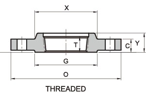
Screwed Flanges

Our range of Screwed Flanges are acknowledge for their high tensile strength and durability. The Screwed Flanges are available in various dimensional specifications and can be customized as per the specifications of our clients
RANGE : 15 NB UP TO 600 NB IN 150 LBS, 300 LBS, 400 LBS, 600 LBS, 900 LBS, 1500 LBS, 2500 LBS / TABLE 2.5, TABLE 6, TABLE 10, TABLE 16,TABLE 25, TABLE 40, TABLE 64, TABLE 160, TABLE 320, TABLE 400 FORM : SLIP ON, SOCKET WELD, BLIND, LAPPED, SCREWED, WELD NECK, REDUCING, SPECTACLE, SLIP ON BOSS, PLATE, PLATE BLANK, SCREWED BOSS. Nickel & Copper Alloy Nickel Alloy ASTM / ASME SB 564 UNS 2200 ( NICKEL 200 ), UNS 4400 (MONEL 400 ), UNS 8825 INCONEL (825), UNS 6600 (INCONEL 600 ), UNS 6601 ( INCONEL 601 ), UNS 6625 (INCONEL 625), UNS 10276 (HASTELLOY C 276) ASTM / ASME SB 160 UNS 2201 (NICKEL 201) ASTM / ASME SB 472 UNS 8020 (ALLOY 20 / 20 CB 3) Copper Alloy ASTM / ASME SB 61 UNS NO. C 92200 & ASTM / ASME SB 62 UNS NO. C 83600. ASTM / ASME SB 151 UNS NO.70600, 71500, C 70600 ( CU -NI- 90/10), C 71500 ( CU -NI- 70/30) ASTM / ASME SB 152 UNS NO C 10100, C 10200, C 10300, C 10800 , C 12000, C 12200. Stainless & Duplex Steel Stainless Steel ASTM / ASME SA 182 F 304, 304L, 304H, 309H, 310H, 316, 316H , 316L, 316 LN, 317, 317L, 321, 321H, 347, 347 H Duplex Steel ASTM / ASME SA 182 F 44, F 45, F51, F 53, F 55, F 60, F 61. Carbon & Alloy Steel Carbon Steel ASTM / ASME A 105. ASTM / ASME A 350 LF 2. Alloy Steel ASTM / ASME A 182 GR F 5, F 9, F 11, F 12, F 22, F 91.
150lb Threaded Flange-ASME/ANSI B16.5/Standards, Dimensions & Weight
| Pipe Normal Diam. | O.D. Flange | Thk. Of Flange Min | Diam. of Hub | Diameter of Raised Face | Length Hub.Y | Thread Length | Diam. of Bolt Circle | Diam. of Bolt Holes | Number of Bolts | Diam. of Bolts (inch) | KG | LB | |
| inch | dn | O | C | X | G | Y | T | BC | BH | BN | BD | ||
| 1/2″ | 15 | 89.00 | 11.20 | 30.20 | 35.10 | 15.70 | 15.70 | 60.50 | 15.80 | 4 | 1/2″ | 0.4 | 0.9 |
| 3/4″ | 20 | 98.50 | 12.70 | 38.10 | 42.90 | 15.70 | 15.70 | 69.90 | 15.80 | 4 | 1/2″ | 0.7 | 1.5 |
| 1″ | 25 | 108.00 | 14.20 | 49.30 | 50.80 | 17.50 | 17.50 | 79.30 | 15.80 | 4 | 1/2″ | 0.8 | 1.8 |
| 1-1/4″ | 32 | 117.50 | 15.70 | 58.70 | 63.50 | 20.60 | 20.60 | 88.90 | 15.80 | 4 | 1/2″ | 1.2 | 2.6 |
| 1-1/2″ | 40 | 127.00 | 17.50 | 65.00 | 73.20 | 22.40 | 22.40 | 98.60 | 15.80 | 4 | 1/2″ | 1.5 | 3.3 |
| 2″ | 50 | 152.50 | 19.10 | 77.70 | 91.90 | 25.40 | 25.40 | 120.70 | 19.10 | 4 | 5/8″ | 2.3 | 5.1 |
| 2-1/2″ | 65 | 178.00 | 22.40 | 90.40 | 104.60 | 28.40 | 28.40 | 139.70 | 19.10 | 4 | 5/8″ | 3.7 | 8.1 |
| 3″ | 80 | 190.50 | 23.90 | 108.00 | 127.00 | 30.20 | 30.20 | 152.40 | 19.10 | 4 | 5/8″ | 4.1 | 9 |
| 3-1/2″ | 90 | 216.00 | 23.90 | 122.20 | 139.70 | 31.80 | 31.80 | 177.80 | 19.10 | 8 | 5/8″ | 5.1 | 11.2 |
| 4″ | 100 | 228.50 | 23.90 | 134.90 | 157.20 | 33.30 | 33.30 | 190.50 | 19.10 | 8 | 5/8″ | 5.9 | 13 |
| 5″ | 125 | 254.00 | 23.90 | 163.60 | 185.70 | 36.60 | 36.60 | 215.90 | 22.40 | 8 | 3/4″ | 7 | 15.4 |
| 6″ | 150 | 279.50 | 25.40 | 192.00 | 215.90 | 39.60 | 39.60 | 241.30 | 22.40 | 8 | 3/4″ | 8.4 | 18.5 |
| 8″ | 200 | 343.00 | 28.40 | 246.10 | 269.70 | 44.50 | 44.50 | 298.50 | 22.40 | 8 | 3/4″ | 13 | 28.6 |
| 10″ | 250 | 406.50 | 30.20 | 304.80 | 323.90 | 49.30 | 49.30 | 362.00 | 25.40 | 12 | 7/8″ | 18 | 39.5 |
| 12″ | 300 | 482.50 | 31.80 | 365.30 | 381.00 | 55.60 | 55.60 | 431.80 | 25.40 | 12 | 7/8″ | 29 | 64 |
| 14″ | 350 | 533.50 | 35.10 | 400.10 | 412.80 | 57.20 | 57.20 | 476.30 | 28.50 | 12 | 1″ | 39 | 86 |
| 16″ | 400 | 597.00 | 36.60 | 457.20 | 469.90 | 63.50 | 63.50 | 539.80 | 28.50 | 16 | 1″ | 47 | 103 |
| 18″ | 450 | 635.00 | 39.60 | 505.00 | 533.40 | 68.30 | 68.30 | 577.90 | 31.80 | 16 | 1 1/8″ | 57 | 126 |
| 20″ | 500 | 698.50 | 42.90 | 558.80 | 584.20 | 73.20 | 73.20 | 635.00 | 31.80 | 20 | 1 1/8″ | 76 | 167 |
| 24″ | 600 | 813.00 | 47.80 | 663.40 | 692.20 | 82.60 | 82.60 | 749.30 | 35.10 | 20 | 1 1/4″ | 97 | 214 |
300lb Threaded Flange-ASME/ANSI B16.5/Standards, Dimensions & Weight
| Pipe Normal Diam. | O.D. Flange | Thk. Of Flange Min | Diam. of Hub | Diameter of Raised Face | Length Hub.Y | Thread Length. T | Diam. of Bolt Circle | Diam. of Bolt Holes | Number of Bolts | Diam. of Bolts (inch) | Approx. Weight | ||
| inch | dn | O | C | X | G | Y | T | BC | BH | BN | BD | KG/PCS | LB/PCS |
| 1/2″ | 15 | 95.5 | 14.2 | 38.1 | 35.1 | 22.4 | 15.7 | 66.5 | 15.7 | 4 | 1/2″ | 0.7 | 1.5 |
| 3/4″ | 20 | 117. 5 | 15.7 | 47.8 | 42.9 | 25.4 | 15.7 | 82.6 | 19.1 | 4 | 5/8″ | 1.2 | 2.6 |
| 1″ | 25 | 124. 0 | 17.5 | 53.8 | 50.8 | 26.9 | 17.5 | 88.9 | 19.1 | 4 | 5/8″ | 1.4 | 3.1 |
| 1-1/4″ | 32 | 133. 5 | 19.1 | 63.5 | 63.5 | 26.9 | 20.6 | 98.6 | 19.1 | 4 | 5/8″ | 1.9 | 4.2 |
| 1-1/2″ | 40 | 155. 5 | 20.6 | 69.9 | 73.2 | 30.2 | 22.4 | 114.3 | 22.4 | 4 | 5/8″ | 2.8 | 6.2 |
| 2″ | 50 | 165. 0 | 22.4 | 84.1 | 91.9 | 33.3 | 28.4 | 127 | 19.1 | 8 | 5/8″ | 3.3 | 7.3 |
| 2-1/2″ | 65 | 190. 5 | 25.4 | 100.1 | 104.6 | 38.1 | 31.8 | 149.4 | 22.4 | 8 | 3/4″ | 4.6 | 10.1 |
| 3″ | 80 | 209. 5 | 28.4 | 117.3 | 127 | 42.9 | 31.8 | 168.1 | 22.4 | 8 | 3/4″ | 6.3 | 13.9 |
| 3-1/2″ | 90 | 228. 5 | 30.2 | 133.4 | 139.7 | 44.5 | 36.6 | 184.2 | 22.4 | 8 | 3/4″ | 7.8 | 17.2 |
| 4″ | 100 | 254. 0 | 31.8 | 146.1 | 157.2 | 47.8 | 36.6 | 200.2 | 22.4 | 8 | 3/4″ | 10.2 | 22.4 |
| 5″ | 125 | 279. 5 | 35.1 | 177.8 | 185.7 | 50.8 | 42.9 | 235 | 22.4 | 8 | 3/4″ | 12.9 | 28.4 |
| 6″ | 150 | 317. 5 | 36.6 | 206.2 | 215.9 | 52.3 | 46 | 269.7 | 22.4 | 12 | 3/4″ | 16.8 | 37 |
| 8″ | 200 | 381. 0 | 41.1 | 260.4 | 269.7 | 62 | 50.8 | 330.2 | 25.4 | 12 | 7/8″ | 26 | 57.2 |
| 10″ | 250 | 444. 5 | 47.8 | 320.5 | 323.9 | 66.5 | 55.6 | 387.4 | 28.4 | 16 | 1″ | 37.5 | 82.5 |
| 12″ | 300 | 520. 5 | 50.8 | 374.7 | 381 | 73.2 | 60.5 | 450.9 | 31.8 | 16 | 1 1/8″ | 53 | 117 |
| 14″ | 350 | 584. 0 | 53.8 | 425.5 | 412.8 | 76.2 | 63.5 | 514..4 | 31.8 | 20 | 1 1/8″ | 73 | 161 |
| 16″ | 400 | 647. 5 | 57.2 | 482.6 | 469.9 | 82.6 | 68.3 | 571.5 | 35.1 | 20 | 1 1/4″ | 88 | 194 |
| 18″ | 450 | 711. 0 | 60.5 | 533.4 | 533.4 | 88.9 | 69.9 | 628.7 | 35.1 | 24 | 1 1/4″ | 115 | 253 |
| 20″ | 500 | 774. 5 | 63.5 | 587.2 | 584.2 | 95.3 | 73.2 | 685.8 | 35.1 | 24 | 1 1/4″ | 139 | 306 |
| 24″ | 600 | 914. 5 | 69.9 | 701.5 | 692.2 | 106. 4 | 82.6 | 812.8 | 41.1 | 24 | 1 1/2″ | 212 | 467 |
600lb Threaded Flange-ASME/ANSI B16.5/Standards, Dimensions & Weight

| Pipe Normal Diam. | O.D. Flange | Thk. Of Flange Min | Diam. of Hub | Diameter of Raised Face | Length Hub | Thread Length | Diam. of Bolt Circle | Diam. of Bolt Holes | Number of Bolts | Diam. of Bolts (inch) | Approx. Weight | ||
| inch | dn | O | C | X | G | Y | T | BC | BH | BN | BD | KG/PCS | LB/PCS |
| 1/2″ | 15 | 95.5 | 14.2 | 38.1 | 35.1 | 22.4 | 22.4 | 66.5 | 15.7 | 4 | 1/2″ | 0.9 | 2 |
| 3/4″ | 20 | 117. 5 | 15.7 | 47.8 | 42.9 | 25.4 | 27.7 | 82.6 | 19.1 | 4 | 5/8″ | 1.4 | 3.1 |
| 1″ | 25 | 124. 0 | 17.5 | 53.8 | 50.8 | 26.9 | 34.5 | 88.9 | 19.1 | 4 | 5/8″ | 1.8 | 4 |
| 1-1/4″ | 32 | 133. 5 | 20.6 | 63.5 | 63.5 | 28.4 | 43.2 | 98.6 | 19.1 | 4 | 5/8″ | 2.3 | 5 |
| 1-1/2″ | 40 | 155. 5 | 22.4 | 69.9 | 73.2 | 31.8 | 49.5 | 114.3 | 22.4 | 4 | 3/4″ | 3.3 | 7.3 |
| 2″ | 50 | 165. 0 | 25.4 | 84.1 | 91.9 | 36.6 | 62 | 127 | 19.1 | 8 | 5/8″ | 4 | 8.8 |
| 2-1/2″ | 65 | 190. 5 | 28.4 | 100.1 | 104.6 | 41.1 | 74.7 | 149.4 | 22.4 | 8 | 3/4″ | 5.5 | 12.1 |
| 3″ | 80 | 209. 5 | 31.8 | 117.3 | 127 | 46 | 90.7 | 168.1 | 22.4 | 8 | 3/4″ | 7.4 | 16.3 |
| 3-1/2″ | 90 | 228. 5 | 35.1 | 133.4 | 139.7 | 49.3 | 103.4 | 184.2 | 25.4 | 8 | 7/8″ | 9.2 | 20.2 |
| 4″ | 100 | 273. 0 | 38.1 | 152.4 | 157.2 | 53.8 | 116.1 | 215.9 | 25.4 | 8 | 7/8″ | 16.8 | 37 |
| 5″ | 125 | 330. 0 | 44.5 | 189 | 185.7 | 60.5 | 143.8 | 266.7 | 28.4 | 8 | 1″ | 28.5 | 62.8 |
| 6″ | 150 | 355. 5 | 47.8 | 222.3 | 215.9 | 66.5 | 170.7 | 292.1 | 28.4 | 12 | 1″ | 36.2 | 79.8 |
| 8″ | 200 | 419. 0 | 55.6 | 273.1 | 269.7 | 76.2 | 221.5 | 349.3 | 31.8 | 12 | 1 1/8″ | 21.5 | 114 |
| 10″ | 250 | 508. 0 | 63.5 | 342.9 | 323.9 | 85.9 | 276.4 | 431.8 | 35.1 | 16 | 1 1/4″ | 76.2 | 168 |
| 12″ | 300 | 559. 0 | 66.5 | 400.1 | 381 | 91.9 | 327.2 | 489 | 35.1 | 20 | 1 1/4″ | 89.5 | 197 |
| 14″ | 350 | 603. 5 | 69.9 | 431.8 | 412.8 | 93.7 | 359.2 | 527.1 | 38.1 | 20 | 1 3/8″ | 102 | 225 |
| 16″ | 400 | 686. 0 | 76.2 | 495.3 | 469.9 | 106. 4 | 410.5 | 603.3 | 41.1 | 20 | 1 1/2″ | 150 | 330 |
| 18″ | 450 | 743. 0 | 82.6 | 546.1 | 533.4 | 117. 3 | 461.8 | 654.1 | 44.5 | 20 | 1 5/8″ | 180 | 397 |
| 20″ | 500 | 813. 0 | 88.9 | 609.6 | 584.2 | 127. 0 | 513.1 | 723.9 | 44.5 | 24 | 1 5/8″ | 231 | 509 |
| 24″ | 600 | 940. 0 | 101.6 | 717.6 | 692.2 | 139. 7 | 616 | 838.2 | 50.8 | 24 | 1 7/8″ | 330 | 727 |
900lb Threaded Flange-ASME/ANSI B16.5/Standards, Dimensions & Weight

| Pipe Normal Diam. | O.D. Flange | Thk. Of Flange Min | Diam. of Hub | Length Hub | Thread Length. T | Diam. of Bolt Circle | Diam. of Bolt Holes | Number of Bolts | Diam. of Bolts (inch) | Approx. Weight | ||
| inch | dn | O | C | X | Y | T | BC | BH | BN | BD | KG/PCS | LB/PCS |
| 1/2″ | 15 | 120.7 | 22.4 | 38.1 | 31.8 | 22.4 | 82.6 | 22.4 | 4 | 3/4″ | 1.8 | 4 |
| 3/4″ | 20 | 130 | 25.4 | 44.5 | 35.1 | 25.4 | 88.9 | 22.4 | 4 | 3/4″ | 2.3 | 5 |
| 1″ | 25 | 149.4 | 28.4 | 52.3 | 41.1 | 28.4 | 101.6 | 25.4 | 4 | 7/8″ | 3.6 | 7.9 |
| 1-1/4″ | 32 | 158.8 | 28.4 | 63.5 | 41.1 | 30.2 | 111.3 | 25.4 | 4 | 7/8″ | 4.1 | 9 |
| 1-1/2″ | 40 | 177.8 | 31.8 | 69.9 | 44.5 | 31.8 | 124 | 28.4 | 4 | 1″ | 5.4 | 12 |
| 2″ | 50 | 215.9 | 38.1 | 104.6 | 57.2 | 38.1 | 165.1 | 25.4 | 8 | 7/8″ | 10.5 | 23.1 |
| 2-1/2″ | 65 | 244.3 | 41.1 | 124 | 63.5 | 47.8 | 190.5 | 28.4 | 8 | 1″ | 15.8 | 34.8 |
| 3″ | 80 | 241.3 | 38.1 | 127 | 53.8 | 41.1 | 190.5 | 25.4 | 8 | 7/8″ | 12.3 | 27 |
| 4″ | 100 | 292.1 | 44.5 | 158.8 | 69.9 | 47.8 | 235 | 31.8 | 8 | 1 1/8″ | 23.2 | 51 |
| 5″ | 125 | 349.3 | 50.8 | 190.5 | 79.2 | 53.8 | 279.4 | 35.1 | 8 | 1 1/4″ | 37.5 | 82.6 |
| 6″ | 150 | 381 | 55.6 | 235 | 85.9 | 57.2 | 317.5 | 31.8 | 12 | 1 1/8″ | 48.3 | 106 |
| 8″ | 200 | 469.9 | 63.5 | 298.5 | 101.6 | 63.5 | 393.7 | 38.1 | 12 | 1 3/8″ | 75 | 165 |
| 10″ | 250 | 546.1 | 69.9 | 368.3 | 108 | 71.4 | 469.9 | 38.1 | 16 | 1 3/8″ | 110 | 243 |
| 12″ | 300 | 609.6 | 79.2 | 419.1 | 117.3 | 76.2 | 533.4 | 38.1 | 20 | 1 3/8″ | 146 | 322 |
| 14″ | 350 | 641.4 | 85.9 | 450.9 | 130 | 82.6 | 558.8 | 41.1 | 20 | 1 1/2″ | 172 | 379 |
| 16″ | 400 | 704.9 | 88.9 | 508 | 133.4 | 85.9 | 616 | 44.5 | 20 | 1 5/8″ | 192 | 423 |
| 18″ | 450 | 787.4 | 101.6 | 565.2 | 152.4 | 88.9 | 685.8 | 50.8 | 20 | 1 7/8″ | 272 | 600 |
| 20″ | 500 | 857.3 | 108 | 622.3 | 158.8 | 91.9 | 749.3 | 53.8 | 20 | 2″ | 330 | 727 |
| 24″ | 600 | 1041 | 139.7 | 749.3 | 203.2 | 101.6 | 901.7 | 66.5 | 20 | 2 1/2″ | 632 | 1393 |
1500lb Threaded Flange-ASME/ANSI B16.5/Standards, Dimensions & Weight

| Pipe Normal Diam. | O.D. Flange | Thk. Of Flange Min | Diam. of Hub | Length Hub | Thread Length | Diam. of Bolt Circle | Diam. of Bolt Holes | Number of Bolts | Diam. of Bolts (inch) | Approx. Weight | ||
| inch | dn | O | C | X | Y | T | BC | BH | BN | BD | KG/PCS | LB/PCS |
| 1/2″ | 15 | 120.7 | 22.4 | 38.1 | 31.8 | 22.4 | 82.6 | 22.4 | 4 | 3/4″ | 1.8 | 4 |
| 3/4″ | 20 | 130 | 25.4 | 44.5 | 35.1 | 25.4 | 88.9 | 22.4 | 4 | 3/4″ | 2.3 | 5 |
| 1″ | 25 | 149.4 | 28.4 | 52.3 | 41.1 | 28.4 | 101.6 | 25.4 | 4 | 7/8″ | 3.6 | 7.9 |
| 1-1/4″ | 32 | 158.8 | 28.4 | 63.5 | 41.1 | 30.2 | 111.3 | 25.4 | 4 | 7/8″ | 4.1 | 9 |
| 1-1/2″ | 40 | 177.8 | 31.8 | 69.9 | 44.5 | 31.8 | 124 | 28.4 | 4 | 1″ | 5.4 | 12 |
| 2″ | 50 | 215.9 | 38.1 | 104.6 | 57.2 | 38.1 | 165.1 | 25.4 | 8 | 7/8″ | 10.5 | 23.1 |
| 2-1/2″ | 65 | 244.3 | 41.1 | 124 | 63.5 | 47.8 | 190.5 | 28.4 | 8 | 1″ | 15.8 | 34.8 |
| 3″ | 80 | 266.7 | 47.8 | 133.4 | 190.5 | 25.4 | 8 | 7/8″ | 18.5 | 40.8 | ||
| 4″ | 100 | 311.2 | 53.8 | 162.1 | 235 | 31.8 | 8 | 1 1/8″ | 29 | 64 | ||
| 5″ | 125 | 374.7 | 73.2 | 196.9 | 279.4 | 35.1 | 8 | 1 1/4″ | 53 | 117 | ||
| 6″ | 150 | 393.7 | 82.6 | 228.6 | 317.5 | 31.8 | 12 | 1 1/8″ | 61 | 134 | ||
| 8″ | 200 | 482.6 | 91.9 | 292.1 | 393.7 | 38.1 | 12 | 1 3/8″ | 105 | 231 | ||
| 10″ | 250 | 584.2 | 108 | 368.3 | 469.9 | 38.1 | 16 | 1 3/8″ | 172 | 379 | ||
| 12″ | 300 | 673.1 | 124 | 450.9 | 533.4 | 38.1 | 20 | 1 3/8″ | 264 | 582 | ||
| 14″ | 350 | 749.3 | 133.4 | 495.3 | 558.8 | 41.1 | 20 | 1 1/2″ | ||||
| 16″ | 400 | 825.5 | 146.1 | 552.5 | 616 | 44.5 | 20 | 1 5/8″ | ||||
| 18″ | 450 | 914.4 | 162.1 | 596.9 | 685.8 | 50.8 | 20 | 1 7/8″ | ||||
| 20″ | 500 | 984.3 | 177.8 | 641.4 | 749.3 | 53.8 | 20 | 2″ | ||||
| 24″ | 600 | 1168.4 | 203.2 | 762 | 901.7 | 66.5 | 20 | 2 1/2″ |
2500lb Threaded Flange-ASME/ANSI B16.5/Standards, Dimensions & Weight
| Pipe Normal Diam. | O.D. Flange | Thk. Of Flange Min | Diam.of Hub | Length Hub | Thread Length | Diam. of Bolt Circle | Diam. of Bolt Holes | Number of Bolts | Diam. of Bolts (inch) | KG | LB | |
| inch | dn | O | C | X | Y | T | BC | BH | BN | BD | ||
| 1/2″ | 15 | 133.4 | 30.2 | 42.9 | 39.6 | 28.4 | 88.9 | 22.4 | 4 | 3/4″ | 3 | 6.6 |
| 3/4″ | 20 | 139.7 | 31.8 | 50.8 | 42.9 | 31.8 | 95.3 | 22.4 | 4 | 3/4″ | 4 | 8.8 |
| 1″ | 25 | 158.8 | 35.1 | 57.2 | 47.8 | 35.1 | 108 | 25.4 | 4 | 7/8″ | 5 | 11 |
| 1-1/4″ | 32 | 184.2 | 38.1 | 73.2 | 52.3 | 38.1 | 130 | 28.4 | 4 | 1″ | 8 | 17.6 |
| 1-1/2″ | 40 | 203.2 | 44.5 | 79.2 | 60.5 | 44.5 | 146.1 | 31.8 | 4 | 1 1/8″ | 11 | 25 |
| 2″ | 50 | 235 | 50.8 | 95.3 | 69.9 | 50.8 | 171.5 | 28.4 | 8 | 1″ | 17 | 38 |
| 2-1/2″ | 65 | 266.7 | 57.2 | 114.3 | 79.2 | 57.2 | 196.9 | 31.8 | 8 | 1 1/8″ | 25 | 55 |
| 3″ | 80 | 304.8 | 66.5 | 133.4 | 228.6 | 35.1 | 8 | 1 1/4″ | 38 | 83 | ||
| 3-1/2″ | 90 | |||||||||||
| 4″ | 100 | 355.6 | 76.2 | 165.1 | 273.1 | 41.1 | 8 | 1 1/2″ | 58 | 127 | ||
| 5″ | 125 | 419.1 | 91.9 | 203.2 | 323.9 | 47.8 | 8 | 1 3/4″ | 95 | 210 | ||
| 6″ | 150 | 482.6 | 108 | 235 | 368.3 | 53.8 | 8 | 2″ | 146 | 323 | ||
| 8″ | 200 | 552.5 | 127 | 304.8 | 438.2 | 53.8 | 12 | 2″ | 220 | 485 | ||
| 10″ | 250 | 673.1 | 165.1 | 374.7 | 539.8 | 66.5 | 12 | 2 1/2″ | 420 | 925 | ||
| 12″ | 300 | 762 | 184.2 | 441.5 | 619.3 | 73.2 | 12 | 2 3/4″ | 590 | 1300 |

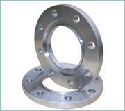
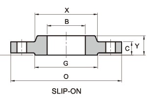
Slip On Flanges
We are involved in offering a range of Slip On Flanges that slide over the end of pipes and can be easily put in place. Ideal for pressure applications, these flanges can be availed in standard specifications and can also be customized as per client’s specific requirement.
RANGE : 15 NB UP TO 600 NB IN 150 LBS, 300 LBS, 400 LBS, 600 LBS, 900 LBS, 1500 LBS, 2500 LBS / TABLE 2.5, TABLE 6, TABLE 10, TABLE 16,TABLE 25, TABLE 40, TABLE 64, TABLE 160, TABLE 320, TABLE 400 FORM : SLIP ON, SOCKET WELD, BLIND, LAPPED, SCREWED, WELD NECK, REDUCING, SPECTACLE, SLIP ON BOSS, PLATE, PLATE BLANK, SCREWED BOSS. Nickel & Copper Alloy Nickel Alloy ASTM / ASME SB 564 UNS 2200 ( NICKEL 200 ), UNS 4400 (MONEL 400 ), UNS 8825 INCONEL (825), UNS 6600 (INCONEL 600 ), UNS 6601 ( INCONEL 601 ), UNS 6625 (INCONEL 625), UNS 10276 (HASTELLOY C 276) ASTM / ASME SB 160 UNS 2201 (NICKEL 201) ASTM / ASME SB 472 UNS 8020 (ALLOY 20 / 20 CB 3) Copper Alloy ASTM / ASME SB 61 UNS NO. C 92200 & ASTM / ASME SB 62 UNS NO. C 83600. ASTM / ASME SB 151 UNS NO. 70600, 71500, C 70600 ( CU -NI- 90/10), C 71500 ( CU -NI- 70/30) ASTM / ASME SB 152 UNS NO C 10100, C 10200, C 10300, C 10800 , C 12000, C 12200. Stainless & Duplex Steel Stainless Steel ASTM / ASME SA 182 F 304, 304L, 304H, 309H, 310H, 316, 316H , 316L, 316 LN, 317, 317L, 321, 321H, 347, 347 H Duplex Steel ASTM / ASME SA 182 F 44, F 45, F51, F 53, F 55, F 60, F 61. Carbon & Alloy Steel Carbon Steel ASTM / ASME A 105. ASTM / ASME A 350 LF 2. Alloy Steel ASTM / ASME A 182 GR F 5, F 9, F 11, F 12, F 22, F 91.
ASME/ANSI B16.5 150lb Slip on Flange/Standards, Dimensions & Weight

| Pipe Normal Diam. | O.D. Flange | Thk. Of Flange Min | Diam. of Hub | Diameter of Raised Face | Length Hub.Y | Bore | Diam. of Bolt Circle | Diam. of Bolt Holes | Number of Bolts | Diam. of Bolts (inch) | KG | LB | |
| inch | dn | O | C | X | G | Y | B | BC | BH | BN | BD | ||
| 1/2″ | 15 | 89.00 | 11.20 | 30.20 | 35.10 | 15.70 | 22.40 | 60.50 | 15.80 | 4 | 1/2″ | 0.4 | 0.9 |
| 3/4″ | 20 | 98.50 | 12.70 | 38.10 | 42.90 | 15.70 | 27.70 | 69.90 | 15.80 | 4 | 1/2″ | 0.7 | 1.5 |
| 1″ | 25 | 108.00 | 14.20 | 49.30 | 50.80 | 17.50 | 34.50 | 79.30 | 15.80 | 4 | 1/2″ | 0.8 | 1.8 |
| 1-1/4″ | 32 | 117.50 | 15.70 | 58.70 | 63.50 | 20.60 | 43.20 | 88.90 | 15.80 | 4 | 1/2″ | 1.2 | 2.6 |
| 1-1/2″ | 40 | 127.00 | 17.50 | 65.00 | 73.20 | 22.40 | 49.50 | 98.60 | 15.80 | 4 | 1/2″ | 1.4 | 3.1 |
| 2″ | 50 | 152.50 | 19.10 | 77.70 | 91.90 | 25.40 | 62.00 | 120.70 | 19.10 | 4 | 5/8″ | 2.2 | 4.8 |
| 2-1/2″ | 65 | 178.00 | 22.40 | 90.40 | 104.60 | 28.40 | 74.70 | 139.70 | 19.10 | 4 | 5/8″ | 3.5 | 7.7 |
| 3″ | 80 | 190.50 | 23.90 | 108.00 | 127.00 | 30.20 | 90.70 | 152.40 | 19.10 | 4 | 5/8″ | 3.8 | 8.4 |
| 3-1/2″ | 90 | 216.00 | 23.90 | 122.20 | 139.70 | 31.80 | 103.40 | 177.80 | 19.10 | 8 | 5/8″ | 5 | 11 |
| 4″ | 100 | 228.50 | 23.90 | 134.90 | 157.20 | 33.30 | 116.10 | 190.50 | 19.10 | 8 | 5/8″ | 5.6 | 12.3 |
| 5″ | 125 | 254.00 | 23.90 | 163.60 | 185.70 | 36.60 | 143.80 | 215.90 | 22.40 | 8 | 3/4″ | 6.5 | 14.3 |
| 6″ | 150 | 279.50 | 25.40 | 192.00 | 215.90 | 39.60 | 170.70 | 241.30 | 22.40 | 8 | 3/4″ | 8.1 | 18 |
| 8″ | 200 | 343.00 | 28.40 | 246.10 | 269.70 | 44.50 | 221.50 | 298.50 | 22.40 | 8 | 3/4″ | 13 | 28.6 |
| 10″ | 250 | 406.50 | 30.20 | 304.80 | 323.90 | 49.30 | 276.40 | 362.00 | 25.40 | 12 | 7/8″ | 18.4 | 40 |
| 12″ | 300 | 482.50 | 31.80 | 365.30 | 381.00 | 55.60 | 327.20 | 431.80 | 25.40 | 12 | 7/8″ | 28.5 | 63 |
| 14″ | 350 | 533.50 | 35.10 | 400.10 | 412.80 | 57.20 | 359.20 | 476.30 | 28.50 | 12 | 1″ | 37.5 | 83 |
| 16″ | 400 | 597.00 | 36.60 | 457.20 | 469.90 | 63.50 | 410.50 | 539.80 | 28.50 | 16 | 1″ | 44.5 | 98 |
| 18″ | 450 | 635.00 | 39.60 | 505.00 | 533.40 | 68.30 | 461.80 | 577.90 | 31.80 | 16 | 1 1/8″ | 54 | 119 |
| 20″ | 500 | 698.50 | 42.90 | 558.80 | 584.20 | 73.20 | 513.10 | 635.00 | 31.80 | 20 | 1 1/8″ | 72 | 158 |
| 24″ | 600 | 813.00 | 47.80 | 663.40 | 692.20 | 82.60 | 616.00 | 749.30 | 35.10 | 20 | 1 1/4″ | 95 | 209 |
Note: 1) Blind Flanges may be made with the same hub as that used for Slip-on Flanges or without hub.
ASME/ANSI B16.5 300lb Slip on Flange/Standards, Dimensions & Weight

| Pipe Normal Diam. | O.D. Flange | Thk. Of Flange Min | Diam. of Hub | Diameter of Raised Face | Length Hub.Y | Bore | Diam. of Bolt Circle | Diam. of Bolt Holes | Number of Bolts | Diam. of Bolts (inch) | Approx. Weight | ||
| inch | dn | O | C | X | G | Y | B | BC | BH | BN | BD | KG/PCS | LB/PCS |
| 1/2″ | 15 | 95.5 | 14.2 | 38.1 | 35.1 | 22.4 | 22.4 | 66.5 | 15.7 | 4 | 1/2″ | 0.7 | 1.5 |
| 3/4″ | 20 | 117. 5 | 15.7 | 47.8 | 42.9 | 25.4 | 27.7 | 82.6 | 19.1 | 4 | 5/8″ | 1.2 | 2.6 |
| 1″ | 25 | 124. 0 | 17.5 | 53.8 | 50.8 | 26.9 | 34.5 | 88.9 | 19.1 | 4 | 5/8″ | 1.4 | 3.1 |
| 1-1/4″ | 32 | 133. 5 | 19.1 | 63.5 | 63.5 | 26.9 | 43.2 | 98.6 | 19.1 | 4 | 5/8″ | 1.8 | 4 |
| 1-1/2″ | 40 | 155. 5 | 20.6 | 69.9 | 73.2 | 30.2 | 49.5 | 114.3 | 22.4 | 4 | 5/8″ | 2.7 | 6 |
| 2″ | 50 | 165. 0 | 22.4 | 84.1 | 91.9 | 33.3 | 62 | 127 | 19.1 | 8 | 5/8″ | 3.2 | 7 |
| 2-1/2″ | 65 | 190. 5 | 25.4 | 100.1 | 104.6 | 38.1 | 74.7 | 149.4 | 22.4 | 8 | 3/4″ | 4.5 | 9.9 |
| 3″ | 80 | 209. 5 | 28.4 | 117.3 | 127 | 42.9 | 90.7 | 168.1 | 22.4 | 8 | 3/4″ | 5.9 | 13 |
| 3-1/2″ | 90 | 228. 5 | 30.2 | 133.4 | 139.7 | 44.5 | 103. 4 | 184.2 | 22.4 | 8 | 3/4″ | 7.5 | 16.5 |
| 4″ | 100 | 254. 0 | 31.8 | 146.1 | 157.2 | 47.8 | 116. 1 | 200.2 | 22.4 | 8 | 3/4″ | 10 | 22 |
| 5″ | 125 | 279. 5 | 35.1 | 177.8 | 185.7 | 50.8 | 143. 8 | 235 | 22.4 | 8 | 3/4″ | 12.5 | 27.5 |
| 6″ | 150 | 317. 5 | 36.6 | 206.2 | 215.9 | 52.3 | 170. 7 | 269.7 | 22.4 | 12 | 3/4″ | 16.5 | 36.4 |
| 8″ | 200 | 381. 0 | 41.1 | 260.4 | 269.7 | 62 | 221. 5 | 330.2 | 25.4 | 12 | 7/8″ | 25.5 | 56 |
| 10″ | 250 | 444. 5 | 47.8 | 320.5 | 323.9 | 66.5 | 276. 4 | 387.4 | 28.4 | 16 | 1″ | 35 | 77 |
| 12″ | 300 | 520. 5 | 50.8 | 374.7 | 381 | 73.2 | 327. 2 | 450.9 | 31.8 | 16 | 1 1/8″ | 52 | 115 |
| 14″ | 350 | 584. 0 | 53.8 | 425.5 | 412.8 | 76.2 | 359. 2 | 514..4 | 31.8 | 20 | 1 1/8″ | 73 | 161 |
| 16″ | 400 | 647. 5 | 57.2 | 482.6 | 469.9 | 82.6 | 410. 5 | 571.5 | 35.1 | 20 | 1 1/4″ | 88 | 194 |
| 18″ | 450 | 711. 0 | 60.5 | 533.4 | 533.4 | 88.9 | 461. 8 | 628.7 | 35.1 | 24 | 1 1/4″ | 115 | 253 |
| 20″ | 500 | 774. 5 | 63.5 | 587.2 | 584.2 | 95.3 | 513. 1 | 685.8 | 35.1 | 24 | 1 1/4″ | 139 | 306 |
| 24″ | 600 | 914. 5 | 69.9 | 701.5 | 692.2 | 106. 4 | 616. 0 | 812.8 | 41.1 | 24 | 1 1/2″ | 212 | 467 |
Note: 1) Blind Flanges may be made with the same hub as that used for Slip-on Flanges or without hub.
ASME/ANSI B16.5 600lb Slip on Flange/Standards, Dimensions & Weight

| Pipe Normal Diam. | O.D. Flange | Thk. Of Flange Min | Diam. of Hub | Diameter of Raised Face | Length Hub | Bore | Diam. of Bolt Circle | Diam. of Bolt Holes | Number of Bolts | Diam. of Bolts (inch) | Approx. Weight | ||
| inch | dn | O | C | X | G | Y | B | BC | BH | BN | BD | KG/PCS | LB/PCS |
| 1/2″ | 15 | 95.5 | 14.2 | 38.1 | 35.1 | 22.4 | 22.9 | 66.5 | 15.7 | 4 | 1/2″ | 0.8 | 1.8 |
| 3/4″ | 20 | 117. 5 | 15.7 | 47.8 | 42.9 | 25.4 | 28.2 | 82.6 | 19.1 | 4 | 5/8″ | 1.4 | 3.1 |
| 1″ | 25 | 124. 0 | 17.5 | 53.8 | 50.8 | 26.9 | 35.1 | 88.9 | 19.1 | 4 | 5/8″ | 1.7 | 3.7 |
| 1-1/4″ | 32 | 133. 5 | 20.6 | 63.5 | 63.5 | 28.4 | 43.7 | 98.6 | 19.1 | 4 | 5/8″ | 2.1 | 4.6 |
| 1-1/2″ | 40 | 155. 5 | 22.4 | 69.9 | 73.2 | 31.8 | 50 | 114.3 | 22.4 | 4 | 3/4″ | 3.1 | 6.8 |
| 2″ | 50 | 165. 0 | 25.4 | 84.1 | 91.9 | 36.6 | 62.5 | 127 | 19.1 | 8 | 5/8″ | 3.9 | 8.6 |
| 2-1/2″ | 65 | 190. 5 | 28.4 | 100.1 | 104.6 | 41.1 | 75.4 | 149.4 | 22.4 | 8 | 3/4″ | 5.4 | 11.9 |
| 3″ | 80 | 209. 5 | 31.8 | 117.3 | 127 | 46 | 91.4 | 168.1 | 22.4 | 8 | 3/4″ | 7.3 | 16.1 |
| 3-1/2″ | 90 | 228. 5 | 35.1 | 133.4 | 139.7 | 49.3 | 104.1 | 184.2 | 25.4 | 8 | 7/8″ | 9 | 19.8 |
| 4″ | 100 | 273. 0 | 38.1 | 152.4 | 157.2 | 53.8 | 116.8 | 215.9 | 25.4 | 8 | 7/8″ | 16.5 | 36..4 |
| 5″ | 125 | 330. 0 | 44.5 | 189 | 185.7 | 60.5 | 144.5 | 266.7 | 28.4 | 8 | 1″ | 28.5 | 62.8 |
| 6″ | 150 | 355. 5 | 47.8 | 222.3 | 215.9 | 66.5 | 171.5 | 292.1 | 28.4 | 12 | 1″ | 36.2 | 79.8 |
| 8″ | 200 | 419. 0 | 55.6 | 273.1 | 269.7 | 76.2 | 222.3 | 349.3 | 31.8 | 12 | 1 1/8″ | 51.5 | 114 |
| 10″ | 250 | 508. 0 | 63.5 | 342.9 | 323.9 | 85.9 | 277.4 | 431.8 | 35.1 | 16 | 1 1/4″ | 76.2 | 168 |
| 12″ | 300 | 559. 0 | 66.5 | 400.1 | 381 | 91.9 | 328.2 | 489 | 35.1 | 20 | 1 1/4″ | 89.5 | 197 |
| 14″ | 350 | 603. 5 | 69.9 | 431.8 | 412.8 | 93.7 | 360.2 | 527.1 | 38.1 | 20 | 1 3/8″ | 102 | 225 |
| 16″ | 400 | 686. 0 | 76.2 | 495.3 | 469.9 | 106. 4 | 411.2 | 603.3 | 41.1 | 20 | 1 1/2″ | 150 | 330 |
| 18″ | 450 | 743. 0 | 82.6 | 546.1 | 533.4 | 117. 3 | 462.3 | 654.1 | 44.5 | 20 | 1 5/8″ | 180 | 397 |
| 20″ | 500 | 813. 0 | 88.9 | 609.6 | 584.2 | 127. 0 | 514.4 | 723.9 | 44.5 | 24 | 1 5/8″ | 231 | 509 |
| 24″ | 600 | 940. 0 | 101.6 | 717.6 | 692.2 | 139. 7 | 616 | 838.2 | 50.8 | 24 | 1 7/8″ | 330 | 727 |
Note: 1) Blind Flanges may be made with the same hub as that used for Slip-on Flanges or without hub. ASME/ANSI B16.5 900lb Slip on Flange/Standards, Dimensions & Weight

| Pipe Normal Diam. | O.D. Flange | Thk. Of Flange Min | Diam. of Hub | Length Hub | Bore | Diam. of Bolt Circle | Diam. of Bolt Holes | Number of Bolts | Diam. of Bolts (inch) | Approx. Weight | ||
| inch | dn | O | C | X | Y | B | BC | BH | BN | BD | KG/PCS | LB/PCS |
| 1/2″ | 15 | 120.7 | 22.4 | 38.1 | 31.8 | 22.4 | 82.6 | 22.4 | 4 | 3/4″ | 1.8 | 4 |
| 3/4″ | 20 | 130 | 25.4 | 44.5 | 35.1 | 27.7 | 88.9 | 22.4 | 4 | 3/4″ | 2.4 | 5.3 |
| 1″ | 25 | 149.4 | 28.4 | 52.3 | 41.1 | 34.5 | 101.6 | 25.4 | 4 | 7/8″ | 3.6 | 7.9 |
| 1-1/4″ | 32 | 158.8 | 28.4 | 63.5 | 41.1 | 43.2 | 111.3 | 25.4 | 4 | 7/8″ | 4.1 | 9 |
| 1-1/2″ | 40 | 177.8 | 31.8 | 69.9 | 44.5 | 49.5 | 124 | 28.4 | 4 | 1″ | 5.4 | 12 |
| 2″ | 50 | 215.9 | 38.1 | 104.6 | 57.2 | 62 | 165.1 | 25.4 | 8 | 7/8″ | 10.5 | 23.1 |
| 2-1/2″ | 65 | 244.3 | 41.1 | 124 | 63.5 | 74.7 | 190.5 | 28.4 | 8 | 1″ | 15.8 | 34.8 |
| 3″ | 80 | 241.3 | 38.1 | 127 | 53.8 | 90.7 | 190.5 | 25.4 | 8 | 7/8″ | 12.3 | 27 |
| 4″ | 100 | 292.1 | 44.5 | 158.8 | 69.9 | 116.1 | 235 | 31.8 | 8 | 1 1/8″ | 23.2 | 51 |
| 5″ | 125 | 349.3 | 50.8 | 190.5 | 79.2 | 143.8 | 279.4 | 35.1 | 8 | 1 1/4″ | 37.5 | 82.6 |
| 6″ | 150 | 381 | 55.6 | 235 | 85.9 | 170.7 | 317.5 | 31.8 | 12 | 1 1/8″ | 48.3 | 106 |
| 8″ | 200 | 469.9 | 63.5 | 298.5 | 101.6 | 221.5 | 393.7 | 38.1 | 12 | 1 3/8″ | 75 | 165 |
| 10″ | 250 | 546.1 | 69.9 | 368.3 | 108 | 276.4 | 469.9 | 38.1 | 16 | 1 3/8″ | 110 | 243 |
| 12″ | 300 | 609.6 | 79.2 | 419.1 | 117.3 | 327.2 | 533.4 | 38.1 | 20 | 1 3/8″ | 146 | 322 |
| 14″ | 350 | 641.4 | 85.9 | 450.9 | 130 | 359.2 | 558.8 | 41.1 | 20 | 1 1/2″ | 172 | 379 |
| 16″ | 400 | 704.9 | 88.9 | 508 | 133.4 | 410.5 | 616 | 44.5 | 20 | 1 5/8″ | 192 | 423 |
| 18″ | 450 | 787.4 | 101.6 | 565.2 | 152.4 | 461.8 | 685.8 | 50.8 | 20 | 1 7/8″ | 272 | 600 |
| 20″ | 500 | 857.3 | 108 | 622.3 | 158.8 | 513.1 | 749.3 | 53.8 | 20 | 2″ | 330 | 727 |
| 24″ | 600 | 1041 | 139.7 | 749.3 | 203.2 | 616 | 901.7 | 66.5 | 20 | 2 1/2″ | 632 | 1393 |
Note: 1) Blind Flanges may be made with the same hub as that used for Slip-on Flanges or without hub.
ASME/ANSI B16.5 1500lb Slip on Flange/Standards, Dimensions & Weight

| Pipe Normal Diam. | O.D. Flange | Thk. Of Flange Min | Diam. of Hub | Length Hub | Bore | Diam. of Bolt Circle | Diam. of Bolt Holes | Number of Bolts | Diam. of Bolts (inch) | Approx. Weight | ||
| inch | dn | O | C | X | Y | B | BC | BH | BN | BD | KG/PCS | LB/PCS |
| 1/2″ | 15 | 120.7 | 22.4 | 38.1 | 31.8 | 22.4 | 82.6 | 22.4 | 4 | 3/4″ | 1.8 | 4 |
| 3/4″ | 20 | 130 | 25.4 | 44.5 | 35.1 | 27.7 | 88.9 | 22.4 | 4 | 3/4″ | 2.4 | 5.3 |
| 1″ | 25 | 149.4 | 28.4 | 52.3 | 41.1 | 34.5 | 101.6 | 25.4 | 4 | 7/8″ | 3.6 | 7.9 |
| 1-1/4″ | 32 | 158.8 | 28.4 | 63.5 | 41.1 | 43.2 | 111.3 | 25.4 | 4 | 7/8″ | 4.1 | 9 |
| 1-1/2″ | 40 | 177.8 | 31.8 | 69.9 | 44.5 | 49.5 | 124 | 28.4 | 4 | 1″ | 5.4 | 12 |
| 2″ | 50 | 215.9 | 38.1 | 104.6 | 57.2 | 62 | 165.1 | 25.4 | 8 | 7/8″ | 10.5 | 23.1 |
| 2-1/2″ | 65 | 244.3 | 41.1 | 124 | 63.5 | 74.7 | 190.5 | 28.4 | 8 | 1″ | 15.8 | 34.8 |
| 3″ | 80 | 266.7 | 47.8 | 133.4 | 190.5 | 25.4 | 8 | 7/8″ | 21.5 | 43 | ||
| 4″ | 100 | 311.2 | 53.8 | 162.1 | 235 | 31.8 | 8 | 1 1/8″ | 31 | 68.3 | ||
| 5″ | 125 | 374.7 | 73.2 | 196.9 | 279.4 | 35.1 | 8 | 1 1/4″ | 58.8 | 130 | ||
| 6″ | 150 | 393.7 | 82.6 | 228.6 | 317.5 | 31.8 | 12 | 1 1/8″ | 74 | 163 | ||
| 8″ | 200 | 482.6 | 91.9 | 292.1 | 393.7 | 38.1 | 12 | 1 3/8″ | 112 | 247 | ||
| 10″ | 250 | 584.2 | 108 | 368.3 | 469.9 | 38.1 | 16 | 1 3/8″ | 184 | 406 | ||
| 12″ | 300 | 673.1 | 124 | 450.9 | 533.4 | 38.1 | 20 | 1 3/8″ | 264 | 581 | ||
| 14″ | 350 | 749.3 | 133.4 | 495.3 | 558.8 | 41.1 | 20 | 1 1/2″ | ||||
| 16″ | 400 | 825.5 | 146.1 | 552.5 | 616 | 44.5 | 20 | 1 5/8″ | ||||
| 18″ | 450 | 914.4 | 162.1 | 596.9 | 685.8 | 50.8 | 20 | 1 7/8″ | ||||
| 20″ | 500 | 984.3 | 177.8 | 641.4 | 749.3 | 53.8 | 20 | 2″ | ||||
| 24″ | 600 | 1168.4 | 203.2 | 762 | 901.7 | 66.5 | 20 | 2 1/2″ |
Note: 1) Blind Flanges may be made with the same hub as that used for Slip-on Flanges or without hub.
ASME/ANSI B16.5 2500lb Slip on Flange/Standards, Dimensions & Weight
| Pipe Normal Diam. | Outside Diameter of Flange | Diameter Bore | thickness of Flange | Diameter of Raised Face | Height of Raised Face | Diameter of Hub at Base | Length through Hub | No. of Holes | Diameter of Holes | Diameter of Bolts | Diameter of Bolt Circle | Weight |
| inch | O | C | G | X | Y | BN | BH | BD | BC | lbs. | ||
| 1/2 | 5.25 | 0.88 | 1.19 | 1.38 | 0.25 | 1.69 | 1.56 | 4 | 0.88 | 3/4 | 3.5 | 7 |
| 3/4 | 5.5 | 1.09 | 1.25 | 1.69 | 0.25 | 2 | 1.69 | 4 | 0.88 | 3/4 | 3.75 | 9 |
| 1 | 6.25 | 1.36 | 1.38 | 2 | 0.25 | 2.25 | 1.88 | 4 | 1 | 7/8 | 4.25 | 12 |
| 1 1/4 | 7.25 | 1.70 | 1.5 | 2.5 | 0.25 | 2.88 | 2.06 | 4 | 1.12 | 1 | 5.12 | 18 |
| 1 1/2 | 8 | 1.95 | 1.75 | 2.88 | 0.25 | 3.12 | 2.38 | 4 | 1.25 | 1 1/8 | 5.75 | 25 |
| 2 | 9.25 | 2.44 | 2 | 3.62 | 0.25 | 3.75 | 2.75 | 8 | 1.12 | 1 | 6.75 | 38 |
| 2 1/2 | 10.5 | 2.94 | 2.25 | 4.12 | 0.25 | 4.5 | 3.13 | 8 | 1.25 | 1 1/8 | 7.75 | 55 |
| 3 | 12 | 3.57 | 2.62 | 5 | 0.25 | 5.25 | 3.63 | 8 | 1.38 | 1 1/4 | 9 | 83 |
| 4 | 14 | 4.57 | 3 | 6.19 | 0.25 | 6.5 | 4.25 | 8 | 1.62 | 1 1/2 | 10.75 | 127 |
| 5 | 16.5 | 5.66 | 3.62 | 7.31 | 0.25 | 8 | 5.13 | 8 | 1.88 | 1 3/4 | 12.75 | 210 |
| 6 | 19 | 6.72 | 4.25 | 8.5 | 0.25 | 9.25 | 6 | 8 | 2.12 | 2 | 14.5 | 323 |
| 8 | 21.75 | 8.72 | 5 | 10.62 | 0.25 | 12 | 7 | 12 | 2.12 | 2 | 17.25 | 485 |
| 10 | 26.5 | 10.88 | 6.5 | 12.75 | 0.25 | 14.75 | 9 | 12 | 2.62 | 2 1/2 | 21.25 | 925 |
| 12 | 30 | 12.88 | 7.25 | 15 | 0.25 | 17.38 | 10 | 12 | 2.88 | 2 3/4 | 24.38 | 1300 |
Note: 1) Blind Flanges may be made with the same hub as that used for Slip-on Flanges or without hub.
Socket Weld Flanges
Our company supply Socket Weld Flanges that are known for their durability and reliability. Our range of quality Socket Weld Flanges offer smooth and flawless performance and their corrosion resistant properties promises high utility.
15 NB UP TO 600 NB IN 150 LBS, 300 LBS, 400 LBS, 600 LBS, 900 LBS, 1500 LBS, 2500 LBS / TABLE 2.5, TABLE 6, TABLE 10, TABLE 16,TABLE 25, TABLE 40, TABLE 64, TABLE 160, TABLE 320, TABLE 400 FORM : SLIP ON, SOCKET WELD, BLIND, LAPPED, SCREWED, WELD NECK, REDUCING, SPECTACLE, SLIP ON BOSS, PLATE, PLATE BLANK, SCREWED BOSS. Nickel & Copper Alloy Nickel Alloy ASTM / ASME SB 564 UNS 2200 ( NICKEL 200 ), UNS 4400 (MONEL 400 ), UNS 8825 INCONEL (825), UNS 6600 (INCONEL 600 ), UNS 6601 ( INCONEL 601 ), UNS 6625 (INCONEL 625), UNS 10276 (HASTELLOY C 276) ASTM / ASME SB 160 UNS 2201 (NICKEL 201) ASTM / ASME SB 472 UNS 8020 (ALLOY 20 / 20 CB 3) Copper Alloy ASTM / ASME SB 61 UNS NO. C 92200 & ASTM / ASME SB 62 UNS NO. C 83600. ASTM / ASME SB 151 UNS NO.70600, 71500, C 70600 ( CU -NI- 90/10), C 71500 ( CU -NI- 70/30) ASTM / ASME SB 152 UNS NO C 10100, C 10200, C 10300, C 10800 , C 12000, C 12200. Stainless & Duplex Steel Stainless Steel ASTM / ASME SA 182 F 304, 304L, 304H, 309H, 310H, 316, 316H , 316L, 316 LN, 317, 317L, 321, 321H, 347, 347 H Duplex Steel ASTM / ASME SA 182 F 44, F 45, F51, F 53, F 55, F 60, F 61. Carbon & Alloy Steel Carbon Steel ASTM / ASME A 105. ASTM / ASME A 350 LF 2. Alloy Steel ASTM / ASME A 182 GR F 5, F 9, F 11, F 12, F 22, F 91.
150lb Socket Welding Flange-ASME/ANSI B16.5/Standards, Dimensions & Weight
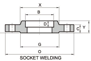
| Pipe Normal Diam. | O.D. Flange | Thk. Of Flange Min | Diam. of Hub | Diameter of Raised Face | Length Hub.Y | Bore | Depth of Socket.D | Diam. of Bolt Circle | Diam. of Bolt Holes | Number of Bolts | Diam. of Bolts (inch) | KG | LB | |
| inch | dn | O | C | X | G | Y | B | D | BC | BH | BN | BD | ||
| 1/2″ | 15 | 89.00 | 11.20 | 30.20 | 35.10 | 15.70 | 22.40 | 9.70 | 60.50 | 15.80 | 4 | 1/2″ | 0.4 | 0.9 |
| 3/4″ | 20 | 98.50 | 12.70 | 38.10 | 42.90 | 15.70 | 27.70 | 11.20 | 69.90 | 15.80 | 4 | 1/2″ | 0.7 | 1.5 |
| 1″ | 25 | 108.00 | 14.20 | 49.30 | 50.80 | 17.50 | 34.50 | 12.70 | 79.30 | 15.80 | 4 | 1/2″ | 0.9 | 2 |
| 1-1/4″ | 32 | 117.50 | 15.70 | 58.70 | 63.50 | 20.60 | 43.20 | 14.20 | 88.90 | 15.80 | 4 | 1/2″ | 1.2 | 2.6 |
| 1-1/2″ | 40 | 127.00 | 17.50 | 65.00 | 73.20 | 22.40 | 49.50 | 15.80 | 98.60 | 15.80 | 4 | 1/2″ | 1.5 | 3.3 |
| 2″ | 50 | 152.50 | 19.10 | 77.70 | 91.90 | 25.40 | 62.00 | 17.50 | 120.70 | 19.10 | 4 | 5/8″ | 2.3 | 5.1 |
| 2-1/2″ | 65 | 178.00 | 22.40 | 90.40 | 104.60 | 28.40 | 74.70 | 19.10 | 139.70 | 19.10 | 4 | 5/8″ | 3.7 | 8.1 |
| 3″ | 80 | 190.50 | 23.90 | 108.00 | 127.00 | 30.20 | 90.70 | 20.60 | 152.40 | 19.10 | 4 | 5/8″ | 4.2 | 9.2 |
| 3-1/2″ | 90 | 216.00 | 23.90 | 122.20 | 139.70 | 31.80 | 103.40 | 177.80 | 19.10 | 8 | 5/8″ | 5.2 | 11.4 | |
| 4″ | 100 | 228.50 | 23.90 | 134.90 | 157.20 | 33.30 | 116.10 | 190.50 | 19.10 | 8 | 5/8″ | 5.9 | 13 | |
| 5″ | 125 | 254.00 | 23.90 | 163.60 | 185.70 | 36.60 | 143.80 | 215.90 | 22.40 | 8 | 3/4″ | 7 | 15.4 | |
| 6″ | 150 | 279.50 | 25.40 | 192.00 | 215.90 | 39.60 | 170.70 | 241.30 | 22.40 | 8 | 3/4″ | 8.4 | 18.5 | |
| 8″ | 200 | 343.00 | 28.40 | 246.10 | 269.70 | 44.50 | 221.50 | 298.50 | 22.40 | 8 | 3/4″ | 12.6 | 27.7 | |
| 10″ | 250 | 406.50 | 30.20 | 304.80 | 323.90 | 49.30 | 276.40 | 362.00 | 25.40 | 12 | 7/8″ | 18 | 39.6 | |
| 12″ | 300 | 482.50 | 31.80 | 365.30 | 381.00 | 55.60 | 327.20 | 431.80 | 25.40 | 12 | 7/8″ | 29.5 | 65 | |
| 14″ | 350 | 533.50 | 35.10 | 400.10 | 412.80 | 57.20 | 359.20 | 476.30 | 28.50 | 12 | 1″ | 38 | 84 | |
| 16″ | 400 | 597.00 | 36.60 | 457.20 | 469.90 | 63.50 | 410.50 | 539.80 | 28.50 | 16 | 1″ | 42 | 93 | |
| 18″ | 450 | 635.00 | 39.60 | 505.00 | 533.40 | 68.30 | 461.80 | 577.90 | 31.80 | 16 | 1 1/8″ | 54 | 120 | |
| 20″ | 500 | 698.50 | 42.90 | 558.80 | 584.20 | 73.20 | 513.10 | 635.00 | 31.80 | 20 | 1 1/8″ | 70 | 155 | |
| 24″ | 600 | 813.00 | 47.80 | 663.40 | 692.20 | 82.60 | 616.00 | 749.30 | 35.10 | 20 | 1 1/4″ | 94 | 207 |
Note: 1) Depth of Socket (D) is covered by ANSI B 16.5 only in sizes through 3 inch, over 3 inch is at the manufacturer’s option.
300lb Socket Welding Flange-ASME/ANSI B16.5/Standards, Dimensions & Weight

| Pipe Normal Diam. | O.D. Flange | Thk. Of Flange Min | Diam. of Hub | Diameter of Raised Face | Length Hub.Y | Bore | Depth of Socket.D | Diam. of Bolt Circle | Diam. of Bolt Holes | Number of Bolts | Diam. of Bolts (inch) | Approx. Weight | ||
| inch | dn | O | C | X | G | Y | B | D | BC | BH | BN | BD | KG/PCS | LB/PCS |
| 1/2″ | 15 | 95.5 | 14.2 | 38.1 | 35.1 | 22.4 | 22.4 | 9. 7 | 66.5 | 15.7 | 4 | 1/2″ | 0.7 | 1.5 |
| 3/4″ | 20 | 117. 5 | 15.7 | 47.8 | 42.9 | 25.4 | 27.7 | 11.2 | 82.6 | 19.1 | 4 | 5/8″ | 1.2 | 2.6 |
| 1″ | 25 | 124. 0 | 17.5 | 53.8 | 50.8 | 26.9 | 34.5 | 12.7 | 88.9 | 19.1 | 4 | 5/8″ | 1.4 | 3.1 |
| 1-1/4″ | 32 | 133. 5 | 19.1 | 63.5 | 63.5 | 26.9 | 43.2 | 14.2 | 98.6 | 19.1 | 4 | 5/8″ | 1.9 | 4.2 |
| 1-1/2″ | 40 | 155. 5 | 20.6 | 69.9 | 73.2 | 30.2 | 49.5 | 15.7 | 114.3 | 22.4 | 4 | 5/8″ | 2.8 | 6.2 |
| 2″ | 50 | 165. 0 | 22.4 | 84.1 | 91.9 | 33.3 | 62 | 17.5 | 127 | 19.1 | 8 | 5/8″ | 3.3 | 7.3 |
| 2-1/2″ | 65 | 190. 5 | 25.4 | 100.1 | 104.6 | 38.1 | 74.7 | 19.1 | 149.4 | 22.4 | 8 | 3/4″ | 4.6 | 10.1 |
| 3″ | 80 | 209. 5 | 28.4 | 117.3 | 127 | 42.9 | 90.7 | 20.6 | 168.1 | 22.4 | 8 | 3/4″ | 6.3 | 13.9 |
| 3-1/2″ | 90 | 228. 5 | 30.2 | 133.4 | 139.7 | 44.5 | 103. 4 | 22.4 | 184.2 | 22.4 | 8 | 3/4″ | 7.8 | 17.2 |
| 4″ | 100 | 254. 0 | 31.8 | 146.1 | 157.2 | 47.8 | 116. 1 | 200.2 | 22.4 | 8 | 3/4″ | 10 | 22 | |
| 5″ | 125 | 279. 5 | 35.1 | 177.8 | 185.7 | 50.8 | 143. 8 | 235 | 22.4 | 8 | 3/4″ | |||
| 6″ | 150 | 317. 5 | 36.6 | 206.2 | 215.9 | 52.3 | 170. 7 | 269.7 | 22.4 | 12 | 3/4″ | |||
| 8″ | 200 | 381. 0 | 41.1 | 260.4 | 269.7 | 62 | 221. 5 | 330.2 | 25.4 | 12 | 7/8″ | |||
| 10″ | 250 | 444. 5 | 47.8 | 320.5 | 323.9 | 66.5 | 276. 4 | 387.4 | 28.4 | 16 | 1″ | |||
| 12″ | 300 | 520. 5 | 50.8 | 374.7 | 381 | 73.2 | 327. 2 | 450.9 | 31.8 | 16 | 1 1/8″ | |||
| 14″ | 350 | 584. 0 | 53.8 | 425.5 | 412.8 | 76.2 | 359. 2 | 514..4 | 31.8 | 20 | 1 1/8″ | |||
| 16″ | 400 | 647. 5 | 57.2 | 482.6 | 469.9 | 82.6 | 410. 5 | 571.5 | 35.1 | 20 | 1 1/4″ | |||
| 18″ | 450 | 711. 0 | 60.5 | 533.4 | 533.4 | 88.9 | 461. 8 | 628.7 | 35.1 | 24 | 1 1/4″ | |||
| 20″ | 500 | 774. 5 | 63.5 | 587.2 | 584.2 | 95.3 | 513. 1 | 685.8 | 35.1 | 24 | 1 1/4″ | |||
| 24″ | 600 | 914. 5 | 69.9 | 701.5 | 692.2 | 106. 4 | 616. 0 | 812.8 | 41.1 | 24 | 1 1/2″ |
Note: 1) Depth of Socket (D) is covered by ANSI B 16.5 only in sizes through 3 inch, over 3 inch is at the manufacturer’s option
600lb Socket Welding Flange-ASME/ANSI B16.5/Standards, Dimensions & Weight

| Pipe Normal Diam. | O.D. Flange | Thk. Of Flange Min | Diam. of Hub | Diameter of Raised Face | Length Hub | Bore | Depth of Socket | Diam. of Bolt Circle | Diam. of Bolt Holes | Number of Bolts | Diam. of Bolts (inch) | Approx. Weight | ||
| inch | dn | O | C | X | G | Y | B | D | BC | BH | BN | BD | KG/PCS | LB/PCS |
| 1/2″ | 15 | 95.5 | 14.2 | 38.1 | 35.1 | 22.4 | 22.9 | 9.7 | 66.5 | 15.7 | 4 | 1/2″ | 1 | 2.2 |
| 3/4″ | 20 | 117. 5 | 15.7 | 47.8 | 42.9 | 25.4 | 28.2 | 11.2 | 82.6 | 19.1 | 4 | 5/8″ | 1.6 | 3.5 |
| 1″ | 25 | 124. 0 | 17.5 | 53.8 | 50.8 | 26.9 | 35.1 | 12.7 | 88.9 | 19.1 | 4 | 5/8″ | 1.8 | 4 |
| 1-1/4″ | 32 | 133. 5 | 20.6 | 63.5 | 63.5 | 28.4 | 43.7 | 14.2 | 98.6 | 19.1 | 4 | 5/8″ | 2.6 | 5.7 |
| 1-1/2″ | 40 | 155. 5 | 22.4 | 69.9 | 73.2 | 31.8 | 50 | 15.7 | 114.3 | 22.4 | 4 | 3/4″ | 3.3 | 7.7 |
| 2″ | 50 | 165. 0 | 25.4 | 84.1 | 91.9 | 36.6 | 62.5 | 17.5 | 127 | 19.1 | 8 | 5/8″ | 3.9 | 8.6 |
| 2-1/2″ | 65 | 190. 5 | 28.4 | 100.1 | 104.6 | 41.1 | 75.4 | 19.1 | 149.4 | 22.4 | 8 | 3/4″ | 6 | 13.2 |
| 3″ | 80 | 209. 5 | 31.8 | 117.3 | 127 | 46 | 91.4 | 20.6 | 168.1 | 22.4 | 8 | 3/4″ | 7.4 | 16.3 |
| 3-1/2″ | 90 | 228. 5 | 35.1 | 133.4 | 139.7 | 49.3 | 104.1 | 184.2 | 25.4 | 8 | 7/8″ | 9.5 | 20.9 | |
| 4″ | 100 | 273. 0 | 38.1 | 152.4 | 157.2 | 53.8 | 116.8 | 215.9 | 25.4 | 8 | 7/8″ | |||
| 5″ | 125 | 330. 0 | 44.5 | 189 | 185.7 | 60.5 | 144.5 | 266.7 | 28.4 | 8 | 1″ | |||
| 6″ | 150 | 355. 5 | 47.8 | 222.3 | 215.9 | 66.5 | 171.5 | 292.1 | 28.4 | 12 | 1″ | |||
| 8″ | 200 | 419. 0 | 55.6 | 273.1 | 269.7 | 76.2 | 222.3 | 349.3 | 31.8 | 12 | 1 1/8″ | |||
| 10″ | 250 | 508. 0 | 63.5 | 342.9 | 323.9 | 85.9 | 277.4 | 431.8 | 35.1 | 16 | 1 1/4″ | |||
| 12″ | 300 | 559. 0 | 66.5 | 400.1 | 381 | 91.9 | 328.2 | 489 | 35.1 | 20 | 1 1/4″ | |||
| 14″ | 350 | 603. 5 | 69.9 | 431.8 | 412.8 | 93.7 | 360.2 | 527.1 | 38.1 | 20 | 1 3/8″ | |||
| 16″ | 400 | 686. 0 | 76.2 | 495.3 | 469.9 | 106. 4 | 411.2 | 603.3 | 41.1 | 20 | 1 1/2″ | |||
| 18″ | 450 | 743. 0 | 82.6 | 546.1 | 533.4 | 117. 3 | 462.3 | 654.1 | 44.5 | 20 | 1 5/8″ | |||
| 20″ | 500 | 813. 0 | 88.9 | 609.6 | 584.2 | 127. 0 | 514.4 | 723.9 | 44.5 | 24 | 1 5/8″ | |||
| 24″ | 600 | 940. 0 | 101.6 | 717.6 | 692.2 | 139. 7 | 616 | 838.2 | 50.8 | 24 | 1 7/8″ |
Note: 1) Depth of Socket (D) is covered by ANSI B 16.5 only in sizes through 3 inch, over 3 inch is at the manufacturer’s option.
1500lb Socket Welding Flange-ASME/ANSI B16.5/Standards, Dimensions & Weight

| Pipe Normal Diam. | O.D. Flange | Thk. Of Flange Min | Diam. of Hub | Length Hub | Bore | Depth of Socket | Diam. of Bolt Circle | Diam. of Bolt Holes | Number of Bolts | Diam. of Bolts (inch) | |
| inch | dn | O | C | X | Y | B | D | BC | BH | BN | BD |
| 1/2″ | 15 | 120.7 | 22.4 | 38.1 | 31.8 | 22.4 | 9.7 | 82.6 | 22.4 | 4 | 3/4″ |
| 3/4″ | 20 | 130 | 25.4 | 44.5 | 35.1 | 27.7 | 11.2 | 88.9 | 22.4 | 4 | 3/4″ |
| 1″ | 25 | 149.4 | 28.4 | 52.3 | 41.1 | 34.5 | 12.7 | 101.6 | 25.4 | 4 | 7/8″ |
| 1-1/4″ | 32 | 158.8 | 28.4 | 63.5 | 41.1 | 43.2 | 14.2 | 111.3 | 25.4 | 4 | 7/8″ |
| 1-1/2″ | 40 | 177.8 | 31.8 | 69.9 | 44.5 | 49.5 | 15.7 | 124 | 28.4 | 4 | 1″ |
| 2″ | 50 | 215.9 | 38.1 | 104.6 | 57.2 | 62 | 17.5 | 165.1 | 25.4 | 8 | 7/8″ |
| 2-1/2″ | 65 | 244.3 | 41.1 | 124 | 63.5 | 74.7 | 19.1 | 190.5 | 28.4 | 8 | 1″ |
| 3″ | 80 | 266.7 | 47.8 | 133.4 | 190.5 | 25.4 | 8 | 7/8″ | |||
| 4″ | 100 | 311.2 | 53.8 | 162.1 | 235 | 31.8 | 8 | 1 1/8″ | |||
| 5″ | 125 | 374.7 | 73.2 | 196.9 | 279.4 | 35.1 | 8 | 1 1/4″ | |||
| 6″ | 150 | 393.7 | 82.6 | 228.6 | 317.5 | 31.8 | 12 | 1 1/8″ | |||
| 8″ | 200 | 482.6 | 91.9 | 292.1 | 393.7 | 38.1 | 12 | 1 3/8″ | |||
| 10″ | 250 | 584.2 | 108 | 368.3 | 469.9 | 38.1 | 16 | 1 3/8″ | |||
| 12″ | 300 | 673.1 | 124 | 450.9 | 533.4 | 38.1 | 20 | 1 3/8″ | |||
| 14″ | 350 | 749.3 | 133.4 | 495.3 | 558.8 | 41.1 | 20 | 1 1/2″ | |||
| 16″ | 400 | 825.5 | 146.1 | 552.5 | 616 | 44.5 | 20 | 1 5/8″ | |||
| 18″ | 450 | 914.4 | 162.1 | 596.9 | 685.8 | 50.8 | 20 | 1 7/8″ | |||
| 20″ | 500 | 984.3 | 177.8 | 641.4 | 749.3 | 53.8 | 20 | 2″ | |||
| 24″ | 600 | 1168.4 | 203.2 | 762 | 901.7 | 66.5 | 20 | 2 1/2″ |
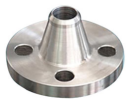
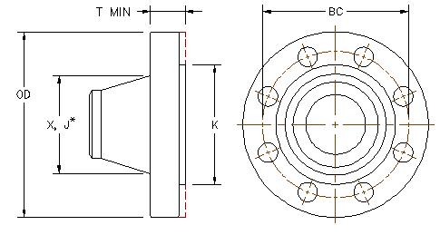
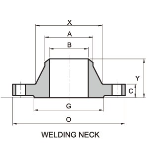
Weld Neck Flanges

Our weld neck flanges are highly durable and reliable and find applications in various industries. Resistant to rust and corrosion, these durable weld neck flanges can be availed in standard as well customized dimensions as per the specific requirement of our clients.
RANGE : 15 NB UP TO 600 NB IN 150 LBS, 300 LBS, 400 LBS, 600 LBS, 900 LBS, 1500 LBS, 2500 LBS / TABLE 2.5, TABLE 6, TABLE 10, TABLE 16,TABLE 25, TABLE 40, TABLE 64, TABLE 160, TABLE 320, TABLE 400 FORM : SLIP ON, SOCKET WELD, BLIND, LAPPED, SCREWED, WELD NECK, REDUCING, SPECTACLE, SLIP ON BOSS, PLATE, PLATE BLANK, SCREWED BOSS. Nickel & Copper Alloy Nickel Alloy ASTM / ASME SB 564 UNS 2200 ( NICKEL 200 ), UNS 4400 (MONEL 400 ), UNS 8825 INCONEL (825), UNS 6600 (INCONEL 600 ), UNS 6601 ( INCONEL 601 ), UNS 6625 (INCONEL 625), UNS 10276 (HASTELLOY C 276) ASTM / ASME SB 160 UNS 2201 (NICKEL 201) ASTM / ASME SB 472 UNS 8020 (ALLOY 20 / 20 CB 3) Copper Alloy ASTM / ASME SB 61 UNS NO. C 92200 & ASTM / ASME SB 62 UNS NO. C 83600. ASTM / ASME SB 151 UNS NO.70600, 71500, C 70600 ( CU -NI- 90/10), C 71500 ( CU -NI- 70/30) ASTM / ASME SB 152 UNS NO C 10100, C 10200, C 10300, C 10800 , C 12000, C 12200. Stainless & Duplex Steel Stainless Steel ASTM / ASME SA 182 F 304, 304L, 304H, 309H, 310H, 316, 316H , 316L, 316 LN, 317, 317L, 321, 321H, 347, 347 H Duplex Steel ASTM / ASME SA 182 F 44, F 45, F51, F 53, F 55, F 60, F 61. Carbon & Alloy Steel Carbon Steel ASTM / ASME A 105. ASTM / ASME A 350 LF 2. Alloy Steel ASTM / ASME A 182 GR F 5, F 9, F 11, F 12, F 22, F 91.
ASME/ANSI B16.5 150LB WN Flange/Standards, Dimensions & Weight

| Pipe Normal Diam. | O.D.Flange | Thk. Of Flange Min | Diam. of Hub | Diameter of Raised Face | Hub Diam. Chamfer of W.N | Length Hub.Y | Bore | Diam. of Bolt Circle | Diam. of Bolt Holes | Number of Bolts | Diam. of Bolts (inch) | KG | LB | |
| inch | dn | O | C | X | G | A | Y | B | BC | BH | BN | BD | ||
| 1/2″ | 15 | 89.00 | 11.20 | 30.20 | 35.10 | 21.30 | 47.80 | 15.80 | 60.50 | 15.80 | 4 | 1/2″ | 0.7 | 1.5 |
| 3/4″ | 20 | 98.50 | 12.70 | 38.10 | 42.90 | 26.70 | 52.30 | 20.80 | 69.90 | 15.80 | 4 | 1/2″ | 0.8 | 1.8 |
| 1″ | 25 | 108.00 | 14.20 | 49.30 | 50.80 | 33.50 | 55.60 | 26.70 | 79.30 | 15.80 | 4 | 1/2″ | 1.1 | 2.4 |
| 1-1/4″ | 32 | 117.50 | 15.70 | 58.70 | 63.50 | 42.20 | 57.20 | 35.10 | 88.90 | 15.80 | 4 | 1/2″ | 1.5 | 3.3 |
| 1-1/2″ | 40 | 127.00 | 17.50 | 65.00 | 73.20 | 48.30 | 62.00 | 40.90 | 98.60 | 15.80 | 4 | 1/2″ | 1.8 | 4 |
| 2″ | 50 | 152.50 | 19.10 | 77.70 | 91.90 | 60.50 | 63.50 | 52.60 | 120.70 | 19.10 | 4 | 5/8″ | 2.7 | 6 |
| 2-1/2″ | 65 | 178.00 | 22.40 | 90.40 | 104.60 | 73.20 | 69.90 | 62.70 | 139.70 | 19.10 | 4 | 5/8″ | 4.4 | 9.8 |
| 3″ | 80 | 190.50 | 23.90 | 108.00 | 127.00 | 88.90 | 69.90 | 78.00 | 152.40 | 19.10 | 4 | 5/8″ | 5.2 | 11.5 |
| 3-1/2″ | 90 | 216.00 | 23.90 | 122.20 | 139.70 | 101.60 | 71.40 | 90.20 | 177.80 | 19.10 | 8 | 5/8″ | 6.4 | 14.2 |
| 4″ | 100 | 228.50 | 23.90 | 134.90 | 157.20 | 114.30 | 76.20 | 102.40 | 190.50 | 19.10 | 8 | 5/8″ | 7.5 | 16.6 |
| 5″ | 125 | 254.00 | 23.90 | 163.60 | 185.70 | 141.20 | 88.90 | 128.30 | 215.90 | 22.40 | 8 | 3/4″ | 9.2 | 20.2 |
| 6″ | 150 | 279.50 | 25.40 | 192.00 | 215.90 | 168.40 | 88.90 | 154.20 | 241.30 | 22.40 | 8 | 3/4″ | 11 | 24.3 |
| 8″ | 200 | 343.00 | 28.40 | 246.10 | 269.70 | 219.20 | 101.60 | 202.70 | 298.50 | 22.40 | 8 | 3/4″ | 18.4 | 40.6 |
| 10″ | 250 | 406.50 | 30.20 | 304.80 | 323.90 | 273.10 | 101.60 | 254.50 | 362.00 | 25.40 | 12 | 7/8″ | 25.5 | 56.2 |
| 12″ | 300 | 482.50 | 31.80 | 365.30 | 381.00 | 323.90 | 114.30 | 304.80 | 431.80 | 25.40 | 12 | 7/8″ | 37 | 81.4 |
| 14″ | 350 | 533.50 | 35.10 | 400.10 | 412.80 | 355.60 | 127.00 | 476.30 | 28.50 | 12 | 1″ | 51 | 113 | |
| 16″ | 400 | 597.00 | 36.60 | 457.20 | 469.90 | 406.40 | 127.00 | 539.80 | 28.50 | 16 | 1″ | 61.5 | 136 | |
| 18″ | 450 | 635.00 | 39.60 | 505.00 | 533.40 | 457.20 | 139.70 | 577.90 | 31.80 | 16 | 1 1/8″ | 71.5 | 158 | |
| 20″ | 500 | 698.50 | 42.90 | 558.80 | 584.20 | 508.00 | 144.50 | 635.00 | 31.80 | 20 | 1 1/8″ | 85 | 187 | |
| 24″ | 600 | 813.00 | 47.80 | 663.40 | 692.20 | 609.60 | 152.40 | 749.30 | 35.10 | 20 | 1 1/4″ | 119 | 262 |
ASME/ANSI B16.5 300LB WN Flange/Standards, Dimensions & Weight
| Pipe Normal Diam. | O.D. Flange | Thk. Of Flange Min | Diam. of Hub | Diameter of Raised Face | Hub Diam. Chamfer of W.N | Length Hub.Y | Bore | Diam. of Bolt Circle | Diam. of Bolt Holes | Number of Bolts | Diam. of Bolts (inch) | Approx. Weight | ||
| inch | dn | O | C | X | G | A | Y | B | BC | BH | BN | BD | KG/PCS | LB/PCS |
| 1/2″ | 15 | 95.5 | 14.2 | 38.1 | 35.1 | 21.3 | 52.3 | 15.7 | 66.5 | 15.7 | 4 | 1/2″ | 0.8 | 1.8 |
| 3/4″ | 20 | 117. 5 | 15.7 | 47.8 | 42.9 | 26.7 | 57.2 | 20.8 | 82.6 | 19.1 | 4 | 5/8″ | 1.4 | 3.1 |
| 1″ | 25 | 124. 0 | 17.5 | 53.8 | 50.8 | 33.5 | 62 | 26.7 | 88.9 | 19.1 | 4 | 5/8″ | 1.7 | 3.7 |
| 1-1/4″ | 32 | 133. 5 | 19.1 | 63.5 | 63.5 | 42.2 | 65 | 35.1 | 98.6 | 19.1 | 4 | 5/8″ | 2.2 | 4.8 |
| 1-1/2″ | 40 | 155. 5 | 20.6 | 69.9 | 73.2 | 48.3 | 68.3 | 40.9 | 114.3 | 22.4 | 4 | 5/8″ | 3.2 | 7 |
| 2″ | 50 | 165. 0 | 22.4 | 84.1 | 91.9 | 60.5 | 69.9 | 52.6 | 127 | 19.1 | 8 | 5/8″ | 3.6 | 7.9 |
| 2-1/2″ | 65 | 190. 5 | 25.4 | 100.1 | 104.6 | 73.2 | 76.2 | 62.7 | 149.4 | 22.4 | 8 | 3/4″ | 5.4 | 12 |
| 3″ | 80 | 209. 5 | 28.4 | 117.3 | 127 | 88.9 | 79.2 | 78 | 168.1 | 22.4 | 8 | 3/4″ | 7.3 | 16.1 |
| 3-1/2″ | 90 | 228. 5 | 30.2 | 133.4 | 139.7 | 101.6 | 81 | 90.2 | 184.2 | 22.4 | 8 | 3/4″ | 8.9 | 19.6 |
| 4″ | 100 | 254. 0 | 31.8 | 146.1 | 157.2 | 114.3 | 85.9 | 102.4 | 200.2 | 22.4 | 8 | 3/4″ | 11.8 | 26 |
| 5″ | 125 | 279. 5 | 35.1 | 177.8 | 185.7 | 141.2 | 98.6 | 128.3 | 235 | 22.4 | 8 | 3/4″ | 16 | 35.2 |
| 6″ | 150 | 317. 5 | 36.6 | 206.2 | 215.9 | 168.4 | 98.6 | 154.2 | 269.7 | 22.4 | 12 | 3/4″ | 20.2 | 44.6 |
| 8″ | 200 | 381. 0 | 41.1 | 260.4 | 269.7 | 219.2 | 111. 3 | 202.7 | 330.2 | 25.4 | 12 | 7/8″ | 31.2 | 68.8 |
| 10″ | 250 | 444. 5 | 47.8 | 320.5 | 323.9 | 273.1 | 117. 3 | 254.5 | 387.4 | 28.4 | 16 | 1″ | 44.3 | 97.5 |
| 12″ | 300 | 520. 5 | 50.8 | 374.7 | 381 | 323.9 | 130. 0 | 304.8 | 450.9 | 31.8 | 16 | 1 1/8″ | 63.5 | 140 |
| 14″ | 350 | 584. 0 | 53.8 | 425.5 | 412.8 | 355.6 | 142. 7 | 514..4 | 31.8 | 20 | 1 1/8″ | 86 | 190 | |
| 16″ | 400 | 647. 5 | 57.2 | 482.6 | 469.9 | 406.4 | 146. 1 | 571.5 | 35.1 | 20 | 1 1/4″ | 112 | 247 | |
| 18″ | 450 | 711. 0 | 60.5 | 533.4 | 533.4 | 457.2 | 158. 8 | 628.7 | 35.1 | 24 | 1 1/4″ | 141 | 310 | |
| 20″ | 500 | 774. 5 | 63.5 | 587.2 | 584.2 | 508 | 162. 1 | 685.8 | 35.1 | 24 | 1 1/4″ | 173 | 382 | |
| 24″ | 600 | 914. 5 | 69.9 | 701.5 | 692.2 | 609.6 | 168. 1 | 812.8 | 41.1 | 24 | 1 1/2″ | 248 | 546 |
Note: 1) 2 mm raised face regularly furnished on Classes 150 and 300 unless otherwise ordered.
ASME/ANSI B16.5 600LB WN Flange/Standards, Dimensions & Weight

| Pipe Normal Diam. | O.D. Flange | Thk. Of Flange Min | Diam. of Hub | Diameter of Raised Face | Hub Diam. Chamfer of W.N | Length Hub | Diam. of Bolt Circle | Diam. of Bolt Holes | Number of Bolts | Diam. of Bolts (inch) | Approx. Weight | ||
| inch | dn | O | C | X | G | A | Y | BC | BH | BN | BD | KG/PCS | LB/PCS |
| 1/2″ | 15 | 95.5 | 14.2 | 38.1 | 35.1 | 22.4 | 52.3 | 66.5 | 15.7 | 4 | 1/2″ | 0.9 | 2 |
| 3/4″ | 20 | 117. 5 | 15.7 | 47.8 | 42.9 | 25.4 | 57.2 | 82.6 | 19.1 | 4 | 5/8″ | 1.6 | 3.5 |
| 1″ | 25 | 124. 0 | 17.5 | 53.8 | 50.8 | 26.9 | 62 | 88.9 | 19.1 | 4 | 5/8″ | 1.9 | 4.2 |
| 1-1/4″ | 32 | 133. 5 | 20.6 | 63.5 | 63.5 | 28.4 | 66.5 | 98.6 | 19.1 | 4 | 5/8″ | 2.6 | 5.8 |
| 1-1/2″ | 40 | 155. 5 | 22.4 | 69.9 | 73.2 | 31.8 | 69.9 | 114.3 | 22.4 | 4 | 3/4″ | 3.6 | 8 |
| 2″ | 50 | 165. 0 | 25.4 | 84.1 | 91.9 | 36.6 | 73.2 | 127 | 19.1 | 8 | 5/8″ | 4.7 | 10.4 |
| 2-1/2″ | 65 | 190. 5 | 28.4 | 100.1 | 104.6 | 41.1 | 79.2 | 149.4 | 22.4 | 8 | 3/4″ | 4.8 | 15 |
| 3″ | 80 | 209. 5 | 31.8 | 117.3 | 127 | 46 | 82.6 | 168.1 | 22.4 | 8 | 3/4″ | 8.7 | 19.3 |
| 3-1/2″ | 90 | 228. 5 | 35.1 | 133.4 | 139.7 | 49.3 | 85.9 | 184.2 | 25.4 | 8 | 7/8″ | 11.6 | 25.5 |
| 4″ | 100 | 273. 0 | 38.1 | 152.4 | 157.2 | 53.8 | 101. 6 | 215.9 | 25.4 | 8 | 7/8″ | 18.4 | 40.5 |
| 5″ | 125 | 330. 0 | 44.5 | 189 | 185.7 | 60.5 | 114. 3 | 266.7 | 28.4 | 8 | 1″ | 31 | 68 |
| 6″ | 150 | 355. 5 | 47.8 | 222.3 | 215.9 | 66.5 | 117. 3 | 292.1 | 28.4 | 12 | 1″ | 37 | 81.4 |
| 8″ | 200 | 419. 0 | 55.6 | 273.1 | 269.7 | 76.2 | 133. 4 | 349.3 | 31.8 | 12 | 1 1/8″ | 54.5 | 120 |
| 10″ | 250 | 508. 0 | 63.5 | 342.9 | 323.9 | 85.9 | 152. 4 | 431.8 | 35.1 | 16 | 1 1/4″ | 98.5 | 195 |
| 12″ | 300 | 559. 0 | 66.5 | 400.1 | 381 | 91.9 | 155. 4 | 489 | 35.1 | 20 | 1 1/4″ | 105 | 231 |
| 14″ | 350 | 603. 5 | 69.9 | 431.8 | 412.8 | 93.7 | 165. 1 | 527.1 | 38.1 | 20 | 1 3/8″ | 150 | 330 |
| 16″ | 400 | 686. 0 | 76.2 | 495.3 | 469.9 | 106.4 | 177. 8 | 603.3 | 41.1 | 20 | 1 1/2″ | 177 | 390 |
| 18″ | 450 | 743. 0 | 82.6 | 546.1 | 533.4 | 117.3 | 184. 2 | 654.1 | 44.5 | 20 | 1 5/8″ | 228 | 503 |
| 20″ | 500 | 813. 0 | 88.9 | 609.6 | 584.2 | 127 | 190. 5 | 723.9 | 44.5 | 24 | 1 5/8″ | 285 | 628 |
| 24″ | 600 | 940. 0 | 101.6 | 717.6 | 692.2 | 139.7 | 203. 2 | 838.2 | 50.8 | 24 | 1 7/8″ | 372 | 820 |
Note: 1) 7 mm raised face regularly furnished above Class 400 unless otherwise ordered.
ASME/ANSI B16.5 900LB WN Flange/Standards, Dimensions & Weight

| Pipe Normal Diam. | O.D. Flange | Thk. Of Flange Min | Diam. of Hub | Length Hub | Bore | Depth of Socket | Diam. of Bolt Circle | Diam. of Bolt Holes | Number of Bolts | Diam. of Bolts (inch) | |
| inch | dn | O | C | X | Y | B | D | BC | BH | BN | BD |
| 1/2″ | 15 | 120.7 | 22.4 | 38.1 | 31.8 | 22.4 | 9.7 | 82.6 | 22.4 | 4 | 3/4″ |
| 3/4″ | 20 | 130 | 25.4 | 44.5 | 35.1 | 27.7 | 11.2 | 88.9 | 22.4 | 4 | 3/4″ |
| 1″ | 25 | 149.4 | 28.4 | 52.3 | 41.1 | 34.5 | 12.7 | 101.6 | 25.4 | 4 | 7/8″ |
| 1-1/4″ | 32 | 158.8 | 28.4 | 63.5 | 41.1 | 43.2 | 14.2 | 111.3 | 25.4 | 4 | 7/8″ |
| 1-1/2″ | 40 | 177.8 | 31.8 | 69.9 | 44.5 | 49.5 | 15.7 | 124 | 28.4 | 4 | 1″ |
| 2″ | 50 | 215.9 | 38.1 | 104.6 | 57.2 | 62 | 17.5 | 165.1 | 25.4 | 8 | 7/8″ |
| 2-1/2″ | 65 | 244.3 | 41.1 | 124 | 63.5 | 74.7 | 19.1 | 190.5 | 28.4 | 8 | 1″ |
| 3″ | 80 | 266.7 | 47.8 | 133.4 | 190.5 | 25.4 | 8 | 7/8″ | |||
| 4″ | 100 | 311.2 | 53.8 | 162.1 | 235 | 31.8 | 8 | 1 1/8″ | |||
| 5″ | 125 | 374.7 | 73.2 | 196.9 | 279.4 | 35.1 | 8 | 1 1/4″ | |||
| 6″ | 150 | 393.7 | 82.6 | 228.6 | 317.5 | 31.8 | 12 | 1 1/8″ | |||
| 8″ | 200 | 482.6 | 91.9 | 292.1 | 393.7 | 38.1 | 12 | 1 3/8″ | |||
| 10″ | 250 | 584.2 | 108 | 368.3 | 469.9 | 38.1 | 16 | 1 3/8″ | |||
| 12″ | 300 | 673.1 | 124 | 450.9 | 533.4 | 38.1 | 20 | 1 3/8″ | |||
| 14″ | 350 | 749.3 | 133.4 | 495.3 | 558.8 | 41.1 | 20 | 1 1/2″ | |||
| 16″ | 400 | 825.5 | 146.1 | 552.5 | 616 | 44.5 | 20 | 1 5/8″ | |||
| 18″ | 450 | 914.4 | 162.1 | 596.9 | 685.8 | 50.8 | 20 | 1 7/8″ | |||
| 20″ | 500 | 984.3 | 177.8 | 641.4 | 749.3 | 53.8 | 20 | 2″ | |||
| 24″ | 600 | 1168.4 | 203.2 | 762 | 901.7 | 66.5 | 20 | 2 1/2″ |
Note: 1) 7 mm raised face regularly furnished above Class 400 unless otherwise ordered. ASME/ANSI B16.5 1500LB WN Flange/Standards, Dimensions & Weight

| Pipe Normal Diam. | O.D. Flange | Thk. Of Flange Min | Diam. of Hub | Hub Diam. Chamfer of W.N | Length Hub | Diam. of Bolt Circle | Diam. of Bolt Holes | Number of Bolts | Diam. of Bolts (inch) | Approx. Weight | ||
| inch | dn | O | C | X | A | Y | BC | BH | BN | BD | KG/PCS | LB/PCS |
| 1/2″ | 15 | 120.7 | 22.4 | 38.1 | 21.3 | 60.5 | 82.6 | 22.4 | 4 | 3/4″ | 2.1 | 4.6 |
| 3/4″ | 20 | 130 | 25.4 | 44.5 | 26.7 | 69.9 | 88.9 | 22.4 | 4 | 3/4″ | 2.7 | 5.9 |
| 1″ | 25 | 149.4 | 28.4 | 52.3 | 33.5 | 73.2 | 101.6 | 25.4 | 4 | 7/8″ | 3.9 | 8.6 |
| 1-1/4″ | 32 | 158.8 | 28.4 | 63.5 | 42.2 | 73.2 | 111.3 | 25.4 | 4 | 7/8″ | 4.5 | 9.9 |
| 1-1/2″ | 40 | 177.8 | 31.8 | 69.9 | 48.3 | 82.6 | 124 | 28.4 | 4 | 1″ | 6.2 | 13.7 |
| 2″ | 50 | 215.9 | 38.1 | 104.6 | 60.5 | 101.6 | 165.1 | 25.4 | 8 | 7/8″ | 11.3 | 24.9 |
| 2-1/2″ | 65 | 244.3 | 41.1 | 124 | 73.2 | 104.6 | 190.5 | 28.4 | 8 | 1″ | 16.3 | 36 |
| 3″ | 80 | 266.7 | 47.8 | 133.4 | 88.9 | 117.3 | 190.5 | 25.4 | 8 | 7/8″ | 21 | 46.3 |
| 4″ | 100 | 311.2 | 53.8 | 162.1 | 114.3 | 124 | 235 | 31.8 | 8 | 1 1/8″ | 31.8 | 70.1 |
| 5″ | 125 | 374.7 | 73.2 | 196.9 | 141.2 | 155.4 | 279.4 | 35.1 | 8 | 1 1/4″ | 59 | 129.8 |
| 6″ | 150 | 393.7 | 82.6 | 228.6 | 168.4 | 171.5 | 317.5 | 31.8 | 12 | 1 1/8″ | 72 | 158 |
| 8″ | 200 | 482.6 | 91.9 | 292.1 | 219.2 | 212.9 | 393.7 | 38.1 | 12 | 1 3/8″ | 124 | 273 |
| 10″ | 250 | 584.2 | 108 | 368.3 | 273.1 | 254 | 469.9 | 38.1 | 16 | 1 3/8″ | 207 | 456 |
| 12″ | 300 | 673.1 | 124 | 450.9 | 323.9 | 282.4 | 533.4 | 38.1 | 20 | 1 3/8″ | 306 | 674 |
| 14″ | 350 | 749.3 | 133.4 | 495.3 | 355.6 | 298.5 | 558.8 | 41.1 | 20 | 1 1/2″ | 416 | 917 |
| 16″ | 400 | 825.5 | 146.1 | 552.5 | 406.4 | 311.2 | 616 | 44.5 | 20 | 1 5/8″ | 567 | 1250 |
| 18″ | 450 | 914.4 | 162.1 | 596.9 | 457.2 | 327.2 | 685.8 | 50.8 | 20 | 1 7/8″ | 736 | 1623 |
| 20″ | 500 | 984.3 | 177.8 | 641.4 | 508 | 355.6 | 749.3 | 53.8 | 20 | 2″ | 929 | 2048 |
| 24″ | 600 | 1168.4 | 203.2 | 762 | 609.6 | 406.4 | 901.7 | 66.5 | 20 | 2 1/2″ | 1504 | 3316 |
Note: 1) 7 mm raised face regularly furnished above Class 400 unless otherwise ordered. ASME/ANSI B16.5 2500LB WN Flange/Standards, Dimensions & Weight

| Nominal Pipe Size | O.D. Flange | Thk. Of Flange Min | Diam. of Hub | Hub Diam.Chamfer of W.N | Length Hub.Y | Diam.of Bolt Circle | Diam.of Bolt Holes | Number of Bolts | Diam. of Bolts (inch) | KG | LB | |
| inch | dn | O | C | X | A | Y | BC | BH | BN | BD | ||
| 1/2″ | 15 | 133.4 | 30.2 | 42.9 | 21.3 | 73.2 | 88.9 | 22.4 | 4 | 3/4″ | 3.2 | 7 |
| 3/4″ | 20 | 139.7 | 31.8 | 50.8 | 26.7 | 79.2 | 95.3 | 22.4 | 4 | 3/4″ | 3.6 | 8 |
| 1″ | 25 | 158.8 | 35.1 | 57.2 | 33.5 | 88.9 | 108 | 25.4 | 4 | 7/8″ | 5.4 | 12 |
| 1-1/4″ | 32 | 184.2 | 38.1 | 73.2 | 42.2 | 95.3 | 130 | 28.4 | 4 | 1″ | 7.8 | 17.2 |
| 1-1/2″ | 40 | 203.2 | 44.5 | 79.2 | 48.3 | 111.3 | 146.1 | 31.8 | 4 | 1 1/8″ | 11.5 | 25.4 |
| 2″ | 50 | 235 | 50.8 | 95.3 | 60.5 | 127 | 171.5 | 28.4 | 8 | 1″ | 19 | 42 |
| 2-1/2″ | 65 | 266.7 | 57.2 | 114.3 | 73.2 | 142.7 | 196.9 | 31.8 | 8 | 1 1/8″ | 24 | 52 |
| 3″ | 80 | 304.8 | 66.5 | 133.4 | 88.9 | 168.1 | 228.6 | 35.1 | 8 | 1 1/4″ | 42.6 | 94 |
| 4″ | 100 | 355.6 | 76.2 | 165.1 | 114.3 | 190.5 | 273.1 | 41.1 | 8 | 1 1/2″ | 64 | 141 |
| 5″ | 125 | 419.1 | 91.9 | 203.2 | 141.2 | 228.6 | 323.9 | 47.8 | 8 | 1 3/4″ | 111 | 244 |
| 6″ | 150 | 482.6 | 108 | 235 | 168.4 | 273.1 | 368.3 | 53.8 | 8 | 2″ | 171 | 378 |
| 8″ | 200 | 552.5 | 127 | 304.8 | 219.2 | 317.5 | 438.2 | 53.8 | 12 | 2″ | 261 | 576 |
| 10″ | 250 | 673.1 | 165.1 | 374.7 | 273.1 | 419.1 | 539.8 | 66.5 | 12 | 2 1/2″ | 485 | 1068 |
| 12″ | 300 | 762 | 184.2 | 441.5 | 323.9 | 463.6 | 619.3 | 73.2 | 12 | 2 3/4″ | 698 | 1539 |
Note: 1) 7 mm raised face regularly furnished above Class 400 unless otherwise ordered
.jpg)
.jpg)
.jpg)
.jpg)
.jpg)
.jpg)
.jpg)
.jpg)
.jpg)
.jpg)
.jpg)
.jpg)
.jpg)
.jpg)
.jpg)
.jpg)
"Our business in life is not to get ahead of others, but to get ahead of our selves."